PART II: This is the second in a three-part series on flow assurance principles and methods. Part I in September dealt with clogged pipelines, wax deposition, and hydrate plugs. Part III in a subsequent issue will focus on coupled velocity and temperature fields in bundled pipelines.
Time lapse velocity field with growing hydrate plug ("red" indicates high speed).
Strong industry interest in deep subsea exploration and production has elevated the importance of "flow assurance modeling," the study of fluid flow under less than ideal circumstances. Standard approaches, for example, focus on simple Newtonian or power law liquids in conventional pipelines. At worst, they consider turbulent flows in circular geometries. However, in the cold ocean environment, sand production, wax precipitation, and hydrate formation can lead to blockages and unplanned economic loss.
Operational variables are far from certain. Even when the flowing fluid is well characterized, significant changes in composition may appear, depending on the whims of the reservoir.
Thus, modern flow assurance methods address every conceivable situation, for example, fluids with wide ranges of properties, pipelines with noncircular cross-sections, and debris beds that come and go. At high flow rates, the resulting turbulence is often modeled using Newtonian methods, although this remains the subject of debate. But, it is at the lower speeds, where "startup" and "impending clog" conditions are found, that velocity profiles become laminar and strongly dependent upon fluid rheology.
This three-part series on flow assurance simulation addresses non-Newtonian flow modeling in clogged pipes, and introduces the subject of "fluid-solids interaction" in evaluating transient flows. These problems are challenging because nonlinearity, unsteadiness, and geometric complexity all interact strongly.
Modeling, engineering
Clogging circular pipe, velocity and apparent viscosity.
In a sense, once fluid rheology and pipe cross-section are prescribed, the modeling problem becomes a mathematical one. However, this statement is only partially true. Pipeline blockages do not suddenly appear. Their growth or erosion is the result of highly dynamic interactions that depend on empirically determined models. The importance of "fluids-solids interaction" was discussed in Part I of this series.
This interaction draws upon "constitutive models" obtained from controlled laboratory experiments. For example, wax growth and erosion might be accurately monitored as a function of well-defined external parameters with the results, then non-dimensionalized to extend their range of validity.
These results would be used in simulations as follows. If (computed) shear stress exceeds known wax yield stress, erosion will result. If it does not, deposition or local equilibrium may be enforced. The exact rates depend on the physical mechanisms involved (buoyancy, centrifugal force due to bends, cohesion characteristics, weighting material particle size and shape, and so on).
Similar rules apply to hydrate growth and erosion, but the geometric form that hydrate accumulations assume is less predictable. Consider hydrate transport in pipelines, flowing in the form of slurries. Under ideal conditions, the slurry remains a "smooth" single-phase mixture with well-defined properties and minimal pressure loss.
But the possibility that crystals may materialize within the fluid and aggregate to build difficult-to-erode plugs cannot be neglected. Such "hydrate plugs" are notoriously resistant to cleaning and pressure removal. Thus, rheological properties should ideally impart high viscous shear stresses at plug boundaries, thereby efficiently making use of frictional rubbing by entrained debris.
In summary, flow assurance modeling involves "rate versus pressure drop" analysis, plus worst case contingency planning focusing on slowly moving flows and startup conditions, and notably, in the presence of wax deposits, debris beds, and hydrate plugs.
The methodology behind flow assurance analysis combines the best features behind mathematics and rigorous laboratory investigation, making it a truly integrated science. These ideas were first developed for cuttings transport in deviated and horizontal wells. Let's examine various types of simulations that are possible.
Hydrate plug growth
Rectangular viscous stress components.
Under the right thermodynamic conditions, hydrate crystals can aggregate within the pipe, adhere to its walls, and form "plug-like" structures that are difficult to remove. A growing hydrate, plug formation is simulated using a phenomenological model, where initial nucleation is assumed at the bottom right. In the last "snapshot" shown, a 25% area blockage is responsible for an 80% flow reduction.
But the bad news goes further. The stress environment does not appear to be very erosive, thus reducing the ability of the slurry to "self-clean" the pipeline. How this "plug" behaves with time, as flow rates and pressure drops fluctuate, depends on two erosion mechanisms:
- Isolated debris convected by the central core fluid depends on the "velocity and viscosity product," a physical quantity from "Stokes flow" familiar to chemical engineers. This debris collides with the plug in much the same way insects collide with windshields.
- Viscous stresses imparted by the flow are responsible for continuous rubbing, a "sandpapering" effect that wears down the obstruction. Because they are partly determined by the geometry of the blockage, erosion analyses like these are repeated for different sizes and shapes.
Centrifugal effects due to "up and down" and "sideways wandering" bends also affect velocity gradients, influencing buildup the way soil deposition and erosion occur at opposing sides of meandering streams. Since each of the mechanisms considered so far affects clogging in its own subtle way, detailed engineering simulations often involve "nested do-loops" in which all parameter combinations are studied.
Two properties identified for study are the individual rectangular components of shear rate. They allow engineers to assess the effects of gravity and lateral bends more precisely. The Stokes product, "x" and "y" viscous stress components, and the combined total stress level is shown in another image set.
Interestingly, the bottom right diagram suggests that the "green, northwest" corner of the plug may erode slightly, while the "southeast, dark blue" crevice is likely to clog due to poor cleaning. The "N(?)" denoting apparent viscosity accents its dependence on the shear rate (?), a complicated function of the velocity u(x,y).
Wax deposition results
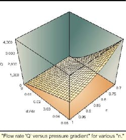
"Flow rate 'Q' versus pressure gradient" for various "n."
In Part I, 12 sequential time-lapse color "photographs" of the evolving velocity field in a clogging circular pipe were given. There, the pipe environment remained at thermal equilibrium with the ocean, so that temperature gradients across the pipe wall did not contribute to azimuthal deposition. That investigation studied buildup from the top down, or from the bottom up, depending on the density of the waxy debris modeled.
For brevity, only three of those velocity "snapshots" are replicated; "red" denotes high core speeds, while "blue" represents lower speeds affected by the no-slip condition. The right side shows how apparent viscosity evolves in the same time frame. Unlike Newtonian fluids, this viscosity varies throughout the cross-section and changes with total flow rate.
How effective the evolving velocity U(x,y) is in eroding depositing wax is seen in the accompanying stress diagrams. The left-side color plots show how erosive stress levels decrease as plugging increases (the vertical extent of the bottom red zone clearly diminishes with time). This explains the bed buildup observed.
While fluid-dynamical means alone may not prevent wax deposition, or hydrate formation, it may be that judicious application of rational simulation tools can minimize the use of chemical inhibitors, or "brute force" thermal heating, which can be exorbitantly expensive.
New modeling concepts
Most pipe flow practitioners are familiar with the concept behind "non-Newtonian" fluids. For ideal fluids like water and air, doubling the pressure gradient will double the flow rate. Since most pressure drops are small anyway, pipeline modeling errors are not all that significant. - Debris buildup leading to clogged (but opened) pipe.
The situation is different for fluids with complicated stress-strain relationships (power law fluids, Bingham plastics, and Herschel-Bulkley flows). "Flow rate versus pressure gradient linearity" rarely applies. In fact, the degree of nonlinearity depends on the pressure drop, plus details related to the geometry.
One quantity significant to pipeline design is "equilibrium radius." Will a given pipeline clog or not? If the rheological properties of the fluid and the mechanical yield properties of the debris lining are known, what is the radius where viscous stresses imparted by the flow exactly equal those needed to erode wax or hydrate coatings?
What is a "good" equilibrium radius? Obviously, one that is "zero" is undesirable; small radii are no better, since pumping requirements can be severe. - -Equilibrium radius depends on fluid rheology.
For the Bingham plastic assumed, numerical results show that high levels of yield stress (tau-y, in psi) and plastic viscosity (as Cp) efficiently "open up" the pipe to flow. For the flow rate used, inner "clog diameters" remain no less than, say, 5 in. But that particular value is dependent on the production rate assumed and the yield stress of the pipe lining, and it will typically vary from rheology to rheology.
Closing remarks
Debris building leading to clogged (but opened) pipe.
There are no clear answers to designing clog-free pipelines. But the possibility of reducing the frequency of flow obstructions using computational simulations exists, because rigorous modeling efficiently extrapolates laboratory data to real world behavior encompassing broad parameter ranges.
In a subsequent Part III, we will examine "bundled pipeline" systems that heat the fluid internally, requiring coupled velocity and thermal modeling. While less attractive from a fabrication perspective, they do provide a flow alternative that is more desirable. Advanced simulation approaches will be discussed, particularly with pipeline economics in mind.
References
- Chin, W. C., "Modern Flow Assurance Methods, Part I: Clogged Pipelines, Wax Deposition, and Hydrate Plugs," Offshore, September 2000.
- Chin, W. C., Borehole Flow Modeling, Gulf Publishing, Houston, 1991.
- Chin, W. C., Computational Rheology for Pipeline and Annular Flow, Gulf Publishing, Houston, 2000.
Acknowledgment
Brown & Root Energy Services and Halliburton Energy Services are acknowledged for the development of solids deposition models (thanks to Raj Amin, Ron Morgan, Harry Smith, and Tin Win for their insights and encouragement). Advanced mapping research and convergence acceleration methods were funded by the US DOE under Grant No. DE-FG03-99ER82895.
Author
Wilson C. Chin holds a PhD from M.I.T. and a MSc from Cal Tech. He is affiliated with StrataMagnetic Software, LLC (Houston) focusing on focusing on computational rheology, reservoir flow analysis, electromagnetic modeling, and software development. He has published 50 related papers, holds 20 oilfield patents, and authored five books on petroleum applications. He may be contacted by email at "[email protected]."


