Simplified well/subsea equipment layout for the Aquila Field Development.
The Aquila deepwater project, developed by ENI-Agip Division, was completed in April 1998 with the first well - Aquila 3 - coming onstream early in March that year. Aquila, located in 850 meters of water in the Otranto Channel, 45 km offshore Brindisi in the southern Adriatic Sea, is the deepest offshore producing field in Europe, and one of the ten deepest in the world.
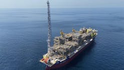
Recoverable reserves from the field have been estimated at 22 million bbl of 36? API oil, from the carbonatic Mesozoic formation in the Umbro-Marchigiano sedimentary basins. Field exploitation is by means of two wells connected directly to the permanently moored floating production, storage, and offloading vessel, via flowlines and control umbilicals. Processed oil is offloaded to a shuttle tanker. Each well has been completed with horizontal subsea christmas trees and a multiplex control system connected to the flowline system.
Reservoir studies showed that oil production would have to be boosted early on to maximize flow rate and oil recovery. The chosen option was single point gas lift injection. Also, analyses of oil samples and experience gained during an extended production test in 1993 dictated the need to prevent asphaltene deposition - so chemicals are injected downhole and their performance is constantly under scrutiny.
To control and monitor reservoir and well performance in real time, SCRAMS (Surface Controlled Reservoir Analysis and Management Systems) from PES are deployed downhole as "intelligent completions." Aquila is one of the first deep offshore fields to deploy such tools.
During the first year of production from the field, bottom hole and wellhead (sea bottom) pressure and temperature data have been acquired continuously and correlated to the production flow rate - the IPR flow performance relationship is calculated for each well in real time. That means updating constantly the reservoir model and subsequent production profile and performance forecasts. The IPR of the initial forecast is checked against the updated one, which influences decisions concerning reservoir management operations and, ultimately, the production profile.
Around one fourth of the field's known reserves - 4.5 million bbl - had been produced by the end of March 1999, with a daily production peak scaled at the end of last year following efforts to optimize production/continuous well monitoring. To date, the IPR of both wells has performed above expectations, something which could not have been achieved without the SCRAMS technology. This in turn has allowed implementation of gas-lift operations on the field to be delayed without impacting the targeted production rate.
Design considerations
Basic criteria prior to embarking on the completion design included the need to:
- Avoid interventions during the field's life (5-7 years).
- Anticipate recovery boosting through artificial (gas) lift.
- Maintain independent access in production/injection of the different zones of the horizontal section of the Aquila 3 well.
- Assure flow, reducing the possibility of asphaltene deposition.
For artificial lift, gas lift was selected following verification of its applicability on Aquila and consideration of gas availability. A single deep injection point (3,300 meters for both wells) was determined, requiring as such higher compression of produced gas (120 bar). In addition, owing to uncertainty over gas lift volumes and pressure required during the field's life, it was decided to provide two different orifice sizes at the injection point, to accommodate possible changes in production conditions.
Another requirement for Aquila 3 came to light after the drilling phase in 1995. The 750-meter long horizontal section revealed different reservoir characteristics in the heel and toe sections, and more importantly, a severe discontinuity in the middle section (thought to be a possible fault conducting water). This prompted design of a special tool which, installed at the top of the horizontal section - in the slanted (45°) part of the well - could improve management of the productive zone during production and stimulation/asphaltene removal injection phases.
Simultaneously, new intelligent completion technology was emerging as an attractive option. The tools designed, manufactured, and install ed on Aquila are an extension of the "intelligent" concept. This means they offer the capability to modify the tool configuration according to changing production conditions via remote activation, in addition to recording and transmission of data.
Horizontal sections
Completions had to be designed as follows:
- Aquila 2 - appraisal well drilled in 1992 vertical to 3,900 meters with a short radius (30°/30 meters) in 8 1/2-in. The final target was 3,953 meters true vertical depth (TVD) with a total horizontal section of 210 meters and a measured depth of 4,161 meters. The well was suspended after an LPT (perforation), with a packer and packer plug to separate the formation from the suspension fluids.
- Aquila 3 - development/delimitation well was drilled in 1995 vertical down to 3,200 meters, then slanted 45° to N-NE to 3,981 meters with a medium radius (4°/30 meters) in 8 1/2-in. The final target was 3,929 meters TVD with a total horizontal section of 750 meters and a measured depth of 4,750 meters. The well was suspended after drilling in polymer mud without testing. The completion configuration of the Aquila 2 drain hole did not change with respect to the LPT configuration. However, that for Aquila 3 has been conceived in consideration of:
- Different permeabilities in the heel (155 meters @ 50 md) and in the toe (185 meters @ 5 md) during initial stimulation, as well as possible future injection of asphaltene-removal products
- Isolation of a possible fault in between (230 meters @ 15 md) expected to drive water.
To achieve this, a 5-in. perforated liner with mixed metallurgy was installed in front of both intervals to be produced. This liner is blank in correspondence of the intermediate zone which has been isolated by means of four (two on each side) external casing packers, to be inflated by cement. The liner was supported by a 9 5/8-in. packer provided on top with a polished bore receptacle designed to create, along with the SCRAMS diverter tool, two separate flow areas.
The first of these areas is constituted by a 2-7/8-in. AMS 28 tubing made up directly below the diverter itself. At the tubing's end is an assembly (4-in.) to seal in the seal bore positioned at 4,346 meters inside the 5-in. liner. The purpose of this tubing is to produce the toe of the horizontal section. The second flow area produces up to the diverter the heel of the horizontal section in the annular space between the 5-in. liner and the outside of the tubing.
The diverter, moving its internal sleeve, puts in communication both flow areas (production/ injection commingled) or alternatively allows production/injection from heel or toe. In addition, it incorporates two pressure and temperature sensors which monitor continuously the annular space and the production tubing.
Mandrel, packer
In the vertical section, both wells have a similar completion incorporating an injection mandrel fed by a 1/4-in. control line. This mandrel is positioned as deep as possible (3,740 meters for Aquila 2; 3,823 meters for Aquila 3) and has been designed to withstand hydrostatic and verification pressure during the installation - the mandrel opens to injection when 2,500 psi control line pressure is applied. The presence of check valves sensitive to the cleanliness of the injected fluid required installation of filters which can be expanded (3,000 psi) should severe clogging arise.
The tubing hanger crossing method is the same used for the safety valve and for the entire hydraulics of the intelligent completion, and relies on special PES FMJ connectors which mate inside the hanger itself. Fluid passage through the tree is achieved through a valve commanded by the tree SCM. Injection rates are regulated through the distribution cabinet located inside the floating production, storage, and offloading (FPSO) turret.
PES' HF 96 47 by 45 production packer was selected as one of the new generation of permanently-retrievable packers, being centrally set without requiring tubing movements during setting. It also allows crossing by several hydraulic/electric lines - two hydraulic and two electrical lines for the Aquila 3 diverter, plus one for the chemical and one for the packer setting, and one for Aquila 2's chemical plus another line for its packer setting. The packer can be set by means of the intelligent completion's hydraulic system through a dedicated outlet, without wireline operations.
Single injection point gas lift has been achieved by installing the operating valve in both wells at 3,300 meters measured depth. This valve is the SCRAMS ICV-GL (internal control valve - gas lift). It has four communication holes between tubing and annulus, phased 90° and drilled parallel to the well axis in the external body.
Two of these holes serve to carry the appropriate gas lift orifice, while the third carries the operative orifice - to be activated in case of total SCRAMS failure - which is normally insulated from the casing by a shear disk (7,500 psi absolute shearing pressure). The fourth allows free circulation when the internal sleeve is in front of it. Each ICV-GL also houses two independent gauges which monitor continuously tubing and annulus pressure and temperature.
The surface controlled subsurface safety valve is Camco's TRM 4PE 4 1/2-in. tubing retrievable piston-activated flapper valve. This is kept open by the HP circuit through the SCM (5,000 psi). With regard to implementation into the subsea production system, the aim was to extend as far as possible the SCRAMS concept of redundancy. Inside the wells, this is achieved by the multi-drop system controlled by two parallel flat packs (each carrying one electrical and one hydraulic line).
FMC technology for multiple hydraulic penetrations through the tree was adopted, based on a quad penetrator that allowed mating of four hydraulic couplers at the tree to hanger interface. Besides the conventional connections to the SCSSV and downhole chemical injection, two lines had to be dedicated to SCRAMS, primary and secondary, fed separately by the SCM.
More complex was the addition of the second electrical penetration which, due to machining constraints, caused the hanger and tree to be one foot higher. The two electrical lines, independent through the umbilical to the FPSO, have therefore been routed to maintain control of the installation while running (vertical outlet through the hanger combined to the SCM's radial outlet via a switching diode) and in parallel to the SCM by means of a separate radial outlet. This is shunted outside the tree to allow an ROV to restore the electrical connection should total control loss occur through the umbilical.
Post-installation lessons
Installation of the two completions was performed by the semisubmersible Jack Bates, starting with Aquila 2 in December 1997 and finishing on Aquila 3 in April 1998. Several problems arose during installation, notably a leak inside the hydraulic central lines operating the two subsea test tree ball safety valves.
The leaks could not be fixed, which necessitated an extensive engineering review of the entire system. However, most of the failures can be ascribed to design limits and, overall, the SCRAMS experience was positive. Problems were assessed and immediately rectified, thereby demonstrating the quality of the basic design. To PES' credit, most of the critical problems were resolved prior to the second Aquila installation.
Among the lessons learned, the following are worth highlighting:
- Flood-resistant SOV chamber: During the descent of the AQ3 system, a sudden rise in pressure within the SOV chamber of both the diverter tool and the ICV-GL were detected. Simple tests demonstrated that HW540 control fluid was leaking into the chamber. Tool performance was badly affected because the interior of the SOV chamber contains gauge wiring connections, position sensors and SOVs. Within a relatively short period (two months) all gauges and position sensors were lost.
Tests performed by PES demonstrated that the pressure barriers between the hydraulic manifold and SOV chamber were inadequate for HP and hydrostatic pressure combined. Welding and SOV torque-up procedures had to be reviewed along with FAT testing enhancement to cater for a 12,500 psi differential pressure between the SOV chamber and the hydraulic system boundary. The operator therefore required the SOV chamber to be made flood resistant. In fact, both tools would have withstood the flooding if the connection had been protected against water based fluid ingress.
- Reference data: Monitoring of SCRAMS' working parameters throughout the field's life is important to anticipate possible failures, especially in applications where the system is used to fine tune production or injection. For this reason, the operator requested PES to make construction test results available during installation. Moreover, specific pre-deployment tests were agreed between the parties to confirm as much functional parameter data as possible. In future, more emphasis will be put on monitoring tool working parameters (i.e. pressure signature during sleeve movement) to predict possible future malfunction.
- Electrical penetration at TH: The TH bottom interface represents the physical boundary between the SCRAMS downhole system and the subsea system. Penetration design selection is a compromise between machining difficulty, pressure barrier reliability and service companies' responsibility during construction and installation. The decision was taken to use PES' FMJ connection, a dual metal to metal seal penetrator that allows testing of the first barrier before the second is activated. Machining such as profile in a 5 ft long solid piece of Inconel 718 was performed successfully by FMC. Nonetheless, serious problems encountered during machining (a drill bit had to be spark eroded from the TH body) could have led to a TH body being discarded, impacting the project schedule. For future applications with such exotic material requirements, ENI-Agip would consider evaluating other less risky solutions.
- Spare equipment: Bearing in mind the interest generated by intelligent completion technology, the operator's approach for future applications would be to rent or share with other operators a complete SCRAMS tool. Spare equipment shouldn't be limited to intelligent SCRAMS tools. Retrieving the completion requires a strategy for a spare flat pack or alternatively a preliminary decision on the maximum acceptable number of splices.


