The danger to oil and gas production today
Jan Olaf Gomnæs
Emerson Process Management
Operators need to ensure that oil and gas reservoirs operate at the very peak of potential. The successful and economic flow of hydrocarbons has never been more important. At the same time, operators face increased threats to flow assurance from hydrates – crystals that form in high-pressure and low-temperature flows where water and natural gas are present.
While the substantial methane-based hydrate deposits in the Gulf of Mexico, for example, represent a potential new source of energy, they also pose a significant obstacle. The growth in deepwater wells with high gas void fraction (GVF), and the high-pressure/low-temperature conditions, increases the threat of hydrates.
Gas hydrates are the most common form of downhole blockages in deepwater wells where gas, water, pressure, and temperature conditions work together thermodynamically. As the natural gas becomes encased in a lattice of ice formed from the water, the danger of blockages in tubing, flow lines, and pipelines increases.
With natural gas an increasingly important energy source, the number of major subsea gas fields is likely to continue to grow (as will offshore, deepwater oil fields). The United States Energy Information Administration estimates world proven natural gas reserves to be around 5,210.8 tcf with much of this wet gas – defined as around 98% to 100% GVF.
The growth in subsea tiebacks (for example, the UK offshore market alone involves over 85 current and future subsea tieback projects, according to the UK-based Energy Industries Council) also has increased the stakes. With tiebacks now more than 100 km (62 mi) long and often with high pressure and low temperature, the emergence of hydrates and solid plugs in the pipes can devastate production rates.
The net result is that operators need to know when the conditions for hydrate formation, such as water breakthrough, are present to have tools to combat them.
With thermodynamic inhibitors such as methanol and ethylene glycol (MEG) and low-dose hydrate inhibitors (LDHIs) currently the most effective ways to prevent hydrates, the focus needs to be on how such inhibitors are distributed subsea. This is to ensure that the hydrate equilibrium curve that operators develop to account for water and gas compositions, and temperature and pressure conditions, is outside the hydrate formation zone.
Wet gas meters
For offshore developments with high pressure and flow rates, and where it is difficult to detect water production profiles in a wet gas well – profiles that can lead to hydrate formation – wet gas meters play a crucial role.
By providing sensitive, accurate, and reliable measurements of the water in the gas stream, operators can take preventative or remedial action with MEG or by the adjusting of the pH in the glycol/water mixture. In this way, operators can optimize production, prevent hydrate, scale and corrosion in the pipelines, and ensure a reliable supply.
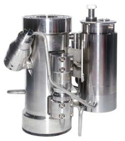
Today’s wet gas meters such as Emerson’s Roxar Wet Gas meters use microwave-based dielectric measurements to generate accurate gas and condensate flow rates based on standard delta pressure devices. The meter detects the resonant frequency in a microwave resonance cavity. The resonant frequency depends on the dielectric properties of the fluid mixture in the cavity. Performance tests on the Roxar meter show it can detect changes in the water production with sensitivity better than +0.005% volume, while the absolute accuracy is +0.1% volume in high GVF (greater than 98.5%) cases.
One such installation is the Greater Gorgon fields, one of the world’s largest untapped natural gas fields. The Gorgon project, 130 km ( 81 mi) offshore Western Australia, is believed to contain over 1 Tcm (35 Tcf) of LNG.
The Roxar subsea meter can operate at depths between 200 and 1,300 m (656 and 4,265 ft), and will provide operator Chevron Australia with real-time, accurate measurements of hydrocarbon flow rates and water production, as well as the online detection of formation water breakthrough.
Other fields vulnerable to hydrate formation using wet gas meters include Ormen Lange field, the largest natural gas field on the Norwegian continental shelf which has no offshore platforms, and the Independence Hub project in the Gulf of Mexico.
In the case of the Ormen Lange, the result is the early detection of water at the wellhead and in the pipelines and a stable supply of natural gas to the UK. Similarly at Independence Hub, by continuously measuring formation water production from each well, Anadarko can operate the wells optimally and ensure that hydrate mitigation is done using appropriate MEG injection.
Regeneration, distribution systems
While wet gas meters provide essential information on water breakthrough, operators still depend on regeneration and distribution systems for accurate injection of hydrate inhibitors. With an increase in hydrate inhibitors added to the gas flow at the wellhead, huge demands are placed on existing regeneration and distribution systems.
Some LDHIs affect the time it takes hydrates to form. In contrast, thermodynamic inhibitors such as MEG tend to require higher injection rates and concentrations. Injection rates must be adjusted if operating parameters such as high subcooling or high water cuts, vary.
There is also the danger of too little or too much methanol. Too little methanol can increase the likelihood for hydrate formation, and the volatility of methanol prices means operators do not want to use more than necessary.
There is, therefore, a need for greater control over measurement and injection of hydrate inhibitors to ensure the correct amounts are used and that injection rates change as conditions change.
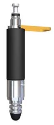
Toward this end, Emerson developed a new high-flow subsea chemical injection valve that aims to give operators more precise control over the flow and chemical dosage rates of hydrate inhibitors such as MEG. This high-flow injection valve is in addition to a low-flow valve are already availabe.
The high-flow valve is based on throttle valve technology first developed in 1990. The first of these remotely operated injection valve went to BP in 1997, and the first fully automated constant-flow injection valve to Statoil in 2002.
The thinking behind the valve was to increase flexibility to adjust the flow, in contrast to a needle valve with narrow flow path and high flow rates. This is achieved by a giving a longer flow path but the same pressure drop. The result is a wider path that allows larger particles to flow through the valve, a lower fluid velocity, and low instances of valve erosion.
There were a number of challenges to developing the latest chemical injection valve.
Contaminating fluid environments, for example, can prevail in deepwater where obstacles to production, such as sand particles, can negatively effect subsea infrastructure. In addition to monitoring sand, the chemical injection valve must operate continuously – ideally without subsea filtration. This is addressed in a number of ways. For example, the injection valve has no choke points – areas which can lead to clogging from sand, mud, or other solids. A high maximum-flow capacity and wide flow path also can prevent clogging.
Aside from the danger of contaminated fluid operating environments, the valve also must operate in high pressures at great water depths with extreme resistance to erosion and abrasion. This was addressed with carefully selected and tested materials such as high grade alloys and ceramics, with the valve incorporating a ceramic flow core for maximum resistance to erosion. The injection valve can operate at pressures of up to 15,000 psi (103 mPa) and depths of 3,000 m (9,842 ft).
Reliability is enhanced by avoiding any moving parts, except when there is a need to adjust flow rates. And, if there is failure, the valve can be retrieved by ROV without need of special tools. During this time, the valve can remain in place to provide a constant injection rate, giving the operator time to prepare for interventions without interrupting production.
The result is a robust and accurate valve with a wide and adjustable flow range and continuous injection rate measurements, regardless of operating conditions. Tests show that the flow measurement accuracy at constant viscosity and temperature is better than +/- 5% and better than +/- 1% with the turbine meter version.
Another design challenge was to make the tools as flexible and compact as possible without compromising performance. This valve weighs less than 60 kg (132 lb) in water, 150 kg (331 lb) total weight, comes with standard communication protocols, and has low power consumption.
The road to integration
The hydrate system needs to be integrated with other measurement solutions and subsea monitoring equipment to increase system performance. This can be in regard to water measurements or the balancing of distributed injections, for example.
In regard to wet gas meters, Emerson is working towards greater integration, where the wet gas meter measures the early onset of formation-water production and the Roxar subsea chemical injection unit takes the necessary preventative action.
In regard to balancing distributed injections, the low-flow chemical valve can operate alongside the high-flow version. In Emerson’s case, low-flow valves include many of the high-flow valve’s features, including laminar flow, high tolerance to contamination, no requirement for subsea filtering, and no moving parts during dosing.
Offshore Articles Archives
View Oil and Gas Articles on PennEnergy.com
