Luis Duque
Zacarias Guimaraes
Victor A. de Almeida
Jose V. Chagas
Robledo Barros
Baker Hughes
Paulo Fonseca
Nelson Siqueira
Petrobras
Naturally occurring hydrates are an abundant source of primary energy, and prove useful in the long-distance transportation of stranded natural gas. However, hydrates in conventional oil and gas drilling and production are an operational and safety problem, and represent potential losses of revenue.
Hydrates can form at pressures and temperatures found in natural gas and oil pipelines, causing blockages, especially when temperatures fall significantly -- such as when closing in a well or flowing gas through a choke. Together with other potential solids depositions, including waxes, asphaltenes, and scales, hydrates pose a serious potential problem for the offshore industry. In addition, remediating hydrate blockages can present significant technical difficulties with major cost implications.
Gas lift system blockages are caused when well fluids enter the gas flowlines, sometimes through leakages in the wet christmas tree (WCT). Sometimes system depressurization is enough for hydrate dissociation. When there is no guarantee that the water content of the gas is below the design values, gas pumped to the subsea gas lift manifold is inhibited by ethanol injection. The theoretical inhibitor rate is calculated using thermodynamics simulators, and adjustments are made based on field data to optimize injection and to ensure hydrate inhibition.
Blockages in production flowlines are mainly caused by restarting wells after an extended shutdown. Even in wells with low basic sediment and water content (5% to 10%), hydrated blockages have formed during production restart. The main causes of blockages in low basic sediment and water wells are water and oil segregation, and the plugging characteristics of the oil in production flowlines that are not cleaned. Hydrate dissociation has been typically achieved by a two-sided depressurization through production and gas flowlines. When these fail, a workover is necessary.
The design criteria for subsea oil production systems regarding hydrates are organized in three aspects: prediction, prevention, and remediation.
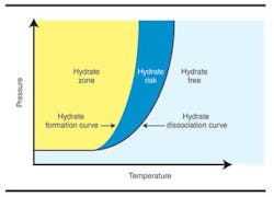
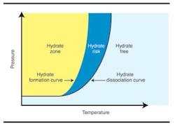
Regarding prediction, the dissociation curve is calculated considering the gas composition at separator conditions. This is a conservative criterion, since gas composition at the separator is richer in heavier hydrocarbon components than elsewhere, and thus more prone to stabilize hydrates. Some crude oils can transport hydrate particles as slurry and delay hydrate formation. Therefore, laboratory tests are required to verify if an oil presents a blockage tendency before proper design can be done. The oil classification governs the prevention requirements, which will be stricter for oil with blockage tendency. Finally, there are some guidelines about how to get thermal-hydraulic performance for steady state or transient flow.
For prevention, the design criteria consider heat retention, heat addition, pressure control, fluid removal, and thermodynamic inhibition. The principal criterion is heat retention through appropriate heat insulation layers. Insulation required for flowlines, risers, and subsea equipment depends on the oil characteristics. For systems handling non-plugging oils, the insulation level should keep the fluid pressure and temperature outside of the hydrate formation envelope during steady-state flow, and provide a cool down window after a shut-in of at least two hours before entering the hydrate envelope. For systems with plugging oils, the cool down time requirement increases to eight hours. The cool down time can be used to depressurize the line or to replace the fluids inside the production line.
Regarding pressure control, the recommendation is to design topsides facilities to simultaneously blow down the production lines of at least four wells within two hours. Similarly, for fluid removal purposes topsides facilities should be designed to permit the replacement of produced fluids from flowlines of six wells within four hours. Diesel is usually the fluid used. If the amount of diesel required exceeds the available volume on the FPU, then alternative methods such as replacing produced fluids by gas lift must be considered.
Injection of thermodynamic inhibitors such as methanol or ethanol is used for prevention–with restriction. Preliminary laboratory tests suggest that injecting these inhibitors in the subsea tree during shut-in is ineffective since it is not easy to promote adequate mixing of the inhibitor and segregated water. Thus, thermodynamic inhibition is considered only as a prevention contingency. Normally there is not a large provision of thermodynamic inhibitor stocks in the FPU, so there is no need for large inhibitor pumping capacities and subsea umbilicals.
For remediation, it is most economical to achieve hydrate dissociation via the FPU. Several depressurizing procedures could be applied, depending on the submarine layout and well conditions. One solution to dissociate flowlines hydrates via FPU is with riser depressurization through coiled tubing. Therefore, it is recommended to provide enough available surface areas on the FPU topsides to hold the equipment needed for blockage location and coiled tubing equipment rig-up. When the FPU cannot be used and a workover rig must be brought in to remediate the problem, the remediation cost increases significantly.
To improve remediation options when conventional FPU-deployed technologies fail, an operator created a team to evaluate alternatives, and to develop procedures, techniques or tools that could reduce the workover rig time when dissociating a hydrate plug through a completion drill pipe riser (DPR) connected to a WCT. Several alternatives were analyzed, including pumping heated fluids to running positive displacements motors and similar options to remove fluid from the DPR.
Finally, the concentric coiled tubing well vacuuming alternative was chosen based upon a simulation predicting that for a 1,500-m (4,921-ft) mudline, the technology could achieve hydrate dissociation in about 6.5 days, compared to about 11.5 days for the conventional solution.
Project development
The goal for the selected technology was to reduce the pressure near the hydrate below the hydrate-association envelope. To achieve this, communication between the workover rig and the FPSO is done via a DPR connected to the WCT. Fluid in the DPR is suctioned into the well vacuuming tool via concentric coiled tubing (CCT) until the hydrate dissociates and the flowlines between the WCT and FPSO are unobstructed. This would be observed at the FPSO using a temperature and pressure transducer (TPT) at the WCT. At 4ºC (39°F) the critical pressure is 145 psi (10 bar), so reducing and maintaining the pressure below that value would maintain the hydrate dissociation.
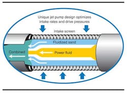
The vacuuming tool is run into the DPR with the CCT. The tool operates using the venturi principle, with water as the power fluid, pumped through the 1-in. inner coiled tubing string. The internal configuration of the vacuuming tool is adjusted to each downhole condition: As the power fluid flows, the nozzle/diffuser section creates a low-pressure zone that vacuums all fluid (power fluid plus fluid from the DPR) through an intake screen and into the CCT system for return to the surface. The fluid is suctioned to the surface through the tool until the hydrostatic pressure inside the DPR is low enough to begin the hydrate dissociation in the flowlines. The fluid returns (power fluid and flowline fluids) come to the surface through the annulus between the inner and outer coiled tubing strings.
For the operations the vacuuming tool had a 21⁄8-in. OD with a 10,000-psi (689-bar) working pressure rating. The tool has a memory gauge for pressure and temperature. Data collected during the job is downloaded and analyzed afterward and compared with real-time TPT data collected.
The tool has two working positions that are switchable via pressure cycled from surface:
- Cleaning mode: Where the tool has front and rear jets to fluidize any solids that may block the well so that they can be swallow and transported to surface
- Suction mode: Where power fluid circulates through the CCT system with no jets, having a higher suctioning effect compared with the cleaning mode. This is the mode used for hydrate dissociation.
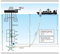
A yard test and two field tests validated the function. The Roncador and Marlin Sul fields in the Campos basin offshore Brazil were chosen because of the long flowlines, low temperatures, and high pressures. For the field tests, the WCT was connected to the rig floor through a 65⁄8-in. DPR and the FPSO connected to the WCT through a flowline wind valve; therefore, hydrate dissociation would establish a direct communication between the workover rig and the FPSO through the WCT.
First field test
The first field test was in Roncador where hydrates blocked two 11.3- km (7-mi) long flowlines: the 6-in. ID production flowline and a 2-in. ID gas lift line. Initially there was no information about where the hydrates were in the lines, or how far they extended into the flowlines.
Removal of the hydrated obstruction was completed by depressurizing the 6-in. flowline through the service flowline (gas lift flowline) via a pig crossover valve at the WCT, as parallel wireline operations at the workover rig prepared to demobilize the workover rig unit.
The initial plan was to keep the communication between the DPR and the flowline open via the wind valve (W1) at the WCT. However, it was possible that the fluid from the newly opened flowline might contain a large volume of gas. Together with the high water percentage in the DPR, such a gas volume was believed to create a high risk of new hydrate formation in the DPR, and, therefore, offered the possibility of getting the CCT stuck. As a result, the following sequence of closing and opening the W1 valve was executed:
- The CCT was run to 1,820 m (5,971 ft), just above the workover BOP, with the W1 valve closed
- The power fluid was pumped at 7,000 psi (483 bar), 0.3 bbl/m, until the fluid inside the DPR was removed to achieve about 1,000 m (3,280 ft.) of space from the bottom, reducing the hydrostatic pressure inside the DPR enough to be outside the hydrate envelope
- The W1 valve was opened, filling the DPR with fluid from the 6-in. production flowline
- The real-time pressure was monitored via TPT until the fluid column stabilized
- The W1 valve was reclosed
- Additional cycles of fluid removal (steps 2-5) were performed until 100% communication between the DPR and the 6-in. production flowline was achieved.
Before the job was successfully completed, 17 cycles were performed, removing about 740 bbl of fluid from the 6-in. flowline: 500 bbl of the total was water and 240 bbl were oil and gas. The total volume of this flowline was 1,210 bbl.
Lessons learned
As a result of lessons learned from the first field test, procedure for the next field test was changed to leave the W1 and W2 valves open while removing the fluid from the DPR. This was expected to reduce the operational time required to achieve hydrate dissociation.
Instead, to minimize the risk of getting the CCT stuck due to formation of hydrates in the DPR, the following actions were recommended:
- Maintain well isolation either by closing Master Valve 1 (m1) on the WCT or by installing a temporary bridge plug on the tubing hanger
- Keep the CCT string moving all the time. If drag force increases, pump rate drops, or DPR pressure increases, pull the BHA to the surface until the parameters return to normal
- Use the TPT sensor in the WCT to continuously monitor the height of fluid column in the DPR while the BHA is in the DPR. Calculations from the operator's production department indicated it would be safe to keep the CCT BHA 10 m (33 ft) above the workover BOP, with fluid up to 100 m above the BHA
- Install a power fluid heater between the filtration unit and the working reel to heat the power fluid up to 60ºC (140°F).
Additional procedural changes planned based on lessons learned from the first trial included:
- To reduce fluid loss from the reel to the DPR, keep the vacuum tool locked in suction mode, as no solids are expected to be encountered in or removed from the flowlines
- Set up an oil/water treatment plant to treat the returned fluids at a minimum of 32 bbl/m
- In the first field test, the vacuum tool filter plugged prematurely and unexpectedly due to impurities in the power fluid. For the second trial, a filtration unit was installed to filter the power fluid before suctioning by the high-pressure pump
- To better control recovered fluid from the DPR, set up a return tank with a real-time measurement system
- Close any possible source of sea water or liquids coming from the E&P unit (UEP) to the flowline or to the WCT, including the valves for chemical injection.
Second field test
The second test was on a well in Marlin Sul field. The production and gas lift flowlines lost communication with the stationary production unit (UEP) due to hydrate plugs in both flowlines. In this case, the mudline at the workover rig was above the mudline at the UEP by 18 m (59 ft). This condition set up another challenge, as gravity alone would not bring all the fluid from the horizontal flowline to the WCT.
For this operation, the maximum level of fluid above the BHA was 130 m (427 ft); previous studies determined that at the downhole temperature for this scenario, hydrate formation would be predicted to begin when the fluid column reached 150 m (492 ft) into the DPR.
After five days of suction work in the DPR, a total of 740 bbl of fluid (water/oil/MEG) were recovered and the communication of both flowlines to the UEP was established. Hydrate dissociation was confirmed by pressurizing both lines with natural gas from the UEP. However, because the communication test was performed with natural gas, a hydrate plug formed again in the production flowline. Ultimately, the vacuuming tool operated over 10 consecutive days with no operational problems.
The biggest challenge in this field test was the mudline depth difference between the WCT and the UEP, which complicated the effort to suction the flowline fluid. Instead of flowing toward the WCT, the fluid was flowing by gravity to the UEP (P-40). As a result, at certain points the vacuum tool was sucking little fluid. After recognizing the problem, operations with the vacuuming tool were suspended, and the flowline was pressurized and depressurized with nitrogen from the workover rig via the DPR. After this some extra fluid was recovered, but the procedure was slow and inefficient. With limited control, the newly formed hydrate plug was not dissociated. Because the operation time was already longer than expected, it was decided to abort the operation from the workover rig (P-23) and achieve the required pressure reduction from the UEP via the gas lift flowline, which was successful.
Conclusions
CCT vacuuming achieved the expected goals of improving control on the parameters during an operation of hydrate dissociation in flowlines offshore Brazil.
The first field test demonstrated that the vacuum tool and CCT technology provided better control over the parameters that govern hydrate blockage formation. However, the risk-avoidance procedures meant it was not possible to directly compare the speed of the vacuum technology against older hydrate removal processes. It is also difficult to compare time of removal because hydrate dissociation involves known and unknown variables. The 16 days of the first field test were considered satisfactory because the time also covered some unrelated operations such as gas lift valves exchanges. In addition, the focus of the operation was a long – 11.6 km (7 mi) – production flowline with a large volume of water to remove.
The second field test was also considered satisfactory. The tool accomplished its objective of the complete removal of the fluid into the DPR and pressure reduction in the flowline to promote hydrate dissociation. As expected, the technique allows better control of the parameters that drive hydrate formation, and the simulated flow parameters were confirmed in the field.
Regarding the operational time reduction, it was concluded that the vacuum technology on CCT could halve the average time to dissociate a hydrate plug in a flowline – meaning completing an operation in five days. After more interventions, the operator and service company expect to optimize procedures based on lessons learned and to develop a database to better analyze operational time savings. The technique will become a recommended practice for hydrate dissociation in flowlines via a workover rig with a DPR.
Acknowledgment
Based on a paper presented at the at the SPE/ICoTA Coiled Tubing & Well Intervention conference held in The Woodlands, Texas, March 27-28, 2012.
