PIPELINE TECHNOLOGY: Pipeline heat loss in rigid, flexible, and pipe-in-pipe deepwater transport
Many deepwater fields have shallow reservoirs, which results in low well-head temperatures. When this situation is combined with long flow-lines and long risers, keeping flow temperature above the critical wax and hydrate formation temperatures requires remedial action. Production fluids are cooled by two phenomena:
- Heat loss through the wall of the pipe
- Heat loss due to expansion of the produced gas in the wellstream.
In deep water, where pressure loss over riser height is large, the latter is usually the most critical. Two main conditions need to be addressed when considering riser system flow assurance:
- Steady state flow condition: Cool down is governed by the cold generation of the gas expansion and by heat losses through the pipe wall. To ensure a desired arrival temperature at the top of the riser, a U value should be specified.
- Transient condition of cool down: In this case, the time required for the pipe and fluid to cool down depends not only on the conductivity of the pipeline materials, but also on their mass and heat capacity. In some cases, the transient condition of heat-up or startup of the pipe may also need attending to.
To assure a certain "topsides arrival temperature" or "minimum cool down time," the most simple solution is to insulate the pipe. Sometimes, however, active heating is required, for example, when heat loss due to gas expansion is such that the requested arrival temperature cannot be achieved, even with a perfectly insulated pipe.
Since the flow condition will change during the field's life, insulation and/or active heating should be adapted to the different conditions. Also, flow assurance aspects of a riser system need to be addressed in tandem with the flowlines to which they are connected.
Pipe-in-pipe
As both conductivity and mechanical resistance of materials decrease with density, materials with good insulation properties are normally mechanically weak, and therefore need to be protected against outside loads such as the hydrostatic pressure. Pipe-in-pipe (PIP) systems provide much better insulation values than single pipelines.
Previously, PIP system choice was often driven by high temperatures for which existing thermoplastic materials were not suited, leading to use of mineral wool as insulation. Microporous materials are more appropriate for PIP systems with a specifically low U value. Coflexip Stena Offshore, which has undertaken four reeled PIP installations, developed and qualified a reelable PIP, incorporating a microporous product with a conductivity as low as 0.02W/m.K.
For a PIP system with 10-in. flowline and a 16-in. carrier, a U value lower than 0.7W/m2.K can be attained. CSO Apache will install the first microporous reeled PIP early this year in the Gulf of Mexico.
In some cases, active heating can be a good alternative to large amounts of passive insulation, especially if the requirement for high insulation only applies to a small part of the field life or during shutdown or startup operations. The two main systems involve electric heating or heating by circulation of hot fluids.
Flexible pipe
For flexible pipes, electric heating has been applied or tested in two different concepts:
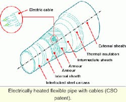
- Heating by electric power through cables within the tensile armor layer: Each heating element comprises two cables enclosed in a steel box, which is installed in place of an armor wire. The remaining armor wires are strong enough to take all the tensile load. Such a system has been implemented offshore, although there are limitations in terms of cable length and maximum power.
- Direct heating through the armor wires themselves: In this case, an armor layer is added to the flexible pipe. The heating layer is insulated from other layers by plastic sheaths. The heating layer wires are assembled in sectors separated by insulating spacers to form the current path for the forward and return directions. Full-scale qualification tests of this system have been conducted which have confirmed the solution's efficiency.
For rigid pipes, two choices are available - fully insulated and grounded direct electric heating (DEH). Regarding the former, the insulation and electrical isolation coating must be 100% reliable, which is not easily achieved. However, it is a very efficient heating system.
A grounded DEH was chosen for the Asgard B pipelay, undertaken by the CSO Apache last spring. Current is injected through a cable at 1,520A, with the return current partly through the flowline (1,060A) and partly through the seawater (460A).
For a flexible pipe, the bundle concept has been used for several years by CSO in the form of the integrated service umbilical. Such risers are in service in the North Sea and in deepwater fields. The same concept is used for the integrated production bundle (IPB), which consists of a:
- Flexible pipe core used for the production fluid.
- Bundle of tubes or hoses spiralled around the core flexible pipe insulation material around the assembly.
Active heating
Main functions of the tubes/hoses are active heating by hot water (or other fluid) circulation, and gas lift - injected at the riser base. The active heating system can be adjusted to the requirements of each project. Both closed or open circuit (discharge to sea at the riser base) are feasible.
Integration of gas lift inside the production riser avoids the need for an extra riser and subsea connection, and also can contribute to heating of the production fluid and, at the same time, injection of hot gas. The IPB is insulated from the cold seawater by a variable thickness insulation material resistant to high pressure loads such as glass syntactic foam. Other functions such as temperature monitoring by optical fiber or hydraulic/electric controls can easily be built into the IPB.
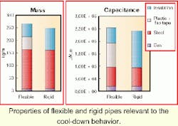
The time required for a pipe and its contents to cool down during a shutdown period depends not only on the conductivity of the different components, but also on their mass and heat. Therefore, the cool-down behavior of a rigid and flexible pipe of identical U value are not the same.
An accompanying figure shows a rigid and a flexible pipe with identical U values (2W/m.K for 1-meter pipe, or 3.2W/m2.K when referring to the rigid pipe's OD).
The insulation coating on the rigid pipe is glass syntactic material. Steel masses for the two pipes are almost identical. The difference arises in the weight of insulation, which is heavier for the rigid pipe than for the flexible pipe. However, the flexible pipe also contains several thermoplastic layers which have a higher mass and heat than the insulation layers and therefore a higher total capacitance. This results in a longer cooldown time for the flexible pipe, as shown above.
Reference
Advances in Riser Technologies Conference, Aberdeen, June 2000.
