OCTG workover risers in deepwater: An alternative solution to drill pipe
Novel solution deployed as part of Gulf of Mexico field development project
Michael Tricarico, Florian Benesch, Alvaro Rodriguez, Corentin Couvreur,Vallourec
Workover risersare an essential part of the subsea well life cycle, allowing operators to access the well during well completion, landing of subsea equipment, and servicing the wells by both chemical and mechanical methods to improve hydrocarbon flow.
As part of a large Gulf of Mexico field development project, Vallourec was asked by a major operator to develop a workover riser to meet stringent environmental and loading requirements including: high fatigue; NACE region 3 sour service; 1,500,000 lb of tension; and 15,000 psi pressure. This challenge was met by designing and testing high-grade sour service pipe along with a specialized and innovative riser connection.
The development led to an Oil Country Tubular Goods (OCTG) solution of 7-in. OD x 0.85-in. wall VM110SS-D VAMTTR HW-NA to meet the harsh environment, while allowing at least 25 cycles of usage. The solution offered all the OCTG grade benefits as compared to a drill pipe solution but with much better sour service performance, and with significantly lower upfront costs. The goal here is to describe the design, testing methods, and results of that effort.
Environment and usage
The primary purpose of a workover and completion/landing riser is to access subsea wells for service. They are used to perform operations in one well and then retrieved to be used in multiple other wells. Workover risers are used in both completion and workover phases of the wells. These functions can include lowering equipment or delivering well cleaning chemicals and using mechanical equipment throughout the life of the well for routine maintenance. These activities are essential for the lifecycle of the well. With all that importance—coupled with the fact that they are often “single barriers” to hydrocarbons leaking into the water—they have to meet very high levels of qualification.
For this specific project a water depth of 8,000 ft, temperature of 220°F, and 15,000 psi working pressure, 1 mm corrosion tolerance, NACE region 3 sour service, and high fatigue cycle resistance described much of the harsh and challenging environment.
Usage of the riser was planned at two to three runs per year. This required a high number (25) of cycles of assembly and disassembly of the threaded connections, known as “make and breaks” or “M&Bs.” For a threaded and coupled connection, this represented a very high number of M&B cycles especially for a high yield strength material. Typically, this has been the weakness of OCTG solutions versus drill pipe risers. By allowing 25 M&Bs, it reduced this issue to allow for a tubular much better at handling the harsh sour service environment than a drill pipe style.
ISO/API specifications
To qualify the riser system for the environment and usage, several qualification tests were required. As a workover riser, the API 17G (ISO13628-7, 2006) specification applied to the system. This specification details the safety factors applied to the design for corrosion, temperature, tension and pressure during design. It also specifies fatigue and basic mechanical testing performance. Because the design chosen is a “threaded and coupled (T&C)” style connection the qualification specification API 5C5 also applied for the static performance. Meeting all the requirements of these stringent specifications necessitated careful design and development testing. Perhaps the most notable requirement is “working pressure” that is assigned by API17G. This requirement states that normal or typical operations have to be less than 60% of the maximum rated pressure of the system. For a 15,000 psi “working pressure” system, or 15k system as commonly referred to, the system must pass a test at 22,500 psi. Similar requirements are placed on the axial loads.
Based on these connection and pipe performance requests, a connection was developed that was then qualified to ISO/FDIS 13679:2011 CALIV and API 17G (ISO13628-7) 2006, putting the VAM TTR HW connection within the most high-performance products in the field.
Loads
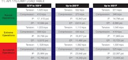
The loads under which the system was to be used were required to be within the limiting factors of both the API 5C5 and API 17G envelopes. The API 17G envelopes were more conservative and limited the system as shown in the table at the various temperatures which were considered as part of the operation. The 15k system was originally designated for the 250°F level. During the project additional interest was expressed in a higher temperature (356°F) for other potential riser applications in the future. The system was then rated for performance under those pressure, tension/compression, and bending loads.
The envelopes in the “API 17G Limit load table” represent the allowable loads defined as normal, extreme, and survival loads in API 17G. The pressure envelopes were defined as 60%, 90%, and 100% of system yield strength taking into account temperature derating factors and corrosion tolerance. Axial loads are defined slightly different as 2/3, 80%, and 100%.
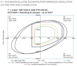
These were the loads as established by the customer and as given by API 17G. The loads tested as per ISO/FDIS 13679:2011 CALIV are defined in below. These confirmed the connection performance per the Von Mises Ellipse (VME) diagram.
Design considerations
There were a number of key design considerations that had to be taken into account in the development of the workover riser. Some of the primary considerations are detailed below.
Pipe –The sour service requirements as well as high pressure mainly drove the material selection. As is usually the case with high performance applications that call for a threaded and coupled product, the coupling material posed the greatest challenge. In this case, the coupling stock was over 8.25-in. OD with an over 1.5-in. wall thickness. The base specification was API 5CT which is typical for oil country tubular goods, with a number of additional end user requirements. As part of these specifications, both pipe and coupling stock needed to pass sour service testing per NACE Method A and Method D per TM0177. These different methods required a total of over 45 days testing multiple groups of specimens. In order to successfully produce material that could meet these requirements, high-grade chemistry as well as specialized heat treatment processes were followed. By using Vallourec expertise developed with years of producing sour service material, the delicate balance between high-strength material and carefully controlled ductility could be reached. Complicating the issue was the very specific size fell just in between the capabilities of the mills at that time. This required the pipe to be produced in one mill (with a piercing process), and coupling stock be produced following a forging process.
Connection –The greatest challenge was successfully achieving 25 M&Bs. A metal-to-metal seal requires interference, meaning metal elastically deforming. A connection with very light interference could be made up many times, but would not be gas tight. A very high interference seal would hold gas tight under all conditions, but would cause so much deformation as to only be made up once without damage. The right balance comes first from experience, and second through mapping that experience in finite element analysis. By knowing the correct interference stress to target, multiple iterations of the connection can be analyzed prior to final design. These can then be compared with previously tested connections. In this case however, while there was a good amount of data on correct design to seal, there was not as much data on the correct interference to ensure such a high number of M&Bs. Typical threaded and coupled connections are rated to 3 to 4 M&Bs. In some cases that has been extended to 10 M&Bs. As much as 25 M&Bs have been attempted in only a few cases. There are different style connections—drill pipe based—that can go well beyond 25 M&Bs, but these solutions struggle with the high sour service requirements relying on difficult-to-qualify welds or large wall thickness variations. This riser threaded and coupled connection can then offer very high sour service resistance on high yield strength material but has also overcome the risk of increased galling. The design then focused on very carefully managing the thread form and fit of threads in addition to the seal interference. As this was an open water riser, the connection was developed with an innovative external water tight seal. The external seal was subject to the same issues on interference as the threads and internal seal. After several iterations of design and FEA simulated load cycles, the right balance was found and the connection was ready to move to physical testing.
For the connection pipe, fatigue testing was conducted on specimens to check their internal pressure capabilities.
Pipe material testing
As is common for pipes produced for riser applications the required dimensions are far beyond API5CT standards. This requires adaptations of the materials and production processes in order to ensure meeting severe requirements, which go even beyond common proprietary grades. Therefore, several mini-rolls were produced prior to the production order to verify the mechanical properties and dimensions of both pipes and coupling material. Beside common testing practices for riser applications like Crack Tip Opening Displacement (CTOD) tests, the requirements on tensile and hardness tests were also extended. The tensile test especially focused on the lower actual yield strength results (110 ksi to 111 ksi), which were revalidated by two additional tests taken from each end 180-degrees apart. In addition, the amount of hardness tests were increased (4 quadrant testing) with a focus on process stability. Sour service resistance was proven by both NACE A and NACE D testing on the actual order.
Connection testing
To meet the challenge of meeting ISO/FDIS 13679:20011 CAL-IV and API 17G testing, a program was designed to combine specimens. This was be done by taking advantage of the threaded and coupled nature of the connections requested. For example, ISO/FDIS 13679:2011, CAL-IV requires five specimens. There are the same number of specimens whether the connection is integral (no coupling) or threaded and coupled. This means that a threaded and coupled connection is testing two connections for every one integral connection. To take advantage of that repeating, Vallourec and the end user agreed to machine each side of the coupling with the required specific configurations, thus combining the specimens while still testing all the configurations.
By using this methodology, the total number of sealability specimens was reduced from four to two which allowed for a large improvement is both cost and schedule, which can often pose great challenges to projects. The Make and Break sample (specimen 5) would remain the same configuration but would be tested to the more difficult requirements of API 17G. This included low and high pressure tests between testing and interchanging of pipe and coupling sides in the so called “round robin style” which mimics the actual field usage of new makeups. The samples then followed the internal pressure, external pressure, bending, tension, compression, and thermal cycles that are prescribed by the ISO/FDIS13679 CALIV protocol, which is regarded as the most difficult to pass of all the 13679/API 5C5 qualification programs.
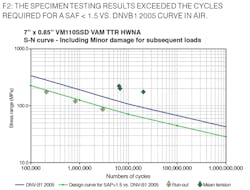
The testing then completed the fatigue requirements with six specimens. In all cases the fatigue specimens had “mean tension” applied in the full-size test specimens by internal water pressure. The pressure pushes against the endcaps which then exert a tension on the pipe and connections. This is typically viewed as a more difficult condition for fatigue testing (though not exclusively required). Three of the specimens were purposely stopped prior to failure to undergo internal pressure testing after fatigue cycles. This helped ensure the specimens could maintain sealability at the highest allowable pressure even after a high number of cycles. The remaining three samples were brought to failure. In all cases the specimens successfully completed testing. The results of the failure samples well exceeded the cycles required for a SAF < 1.5 vs. DNVB1 2005 curve in air, giving a high degree of confidence to claim at a minimum this fatigue life.
Conclusion
Designing a pipe and connection for the highly critical workover/completion/landing riser harsh environment involves satisfying both difficult service conditions and stringent ruling standards. Through experience, careful design, and innovation, Vallourec developed the VAM TTR HW; a high-performance threaded and coupled riser connection that successfully completed the rigorous requirements. This allowed for a solution able to meet both the difficult environment of 25 M&Bs in a NACE region 3 environment with 15,000 psi working pressure as well as allow for a lower cost versus drill pipe style. •
