M. Wiig, E. Berg, J.M. Kjaerefjord, M. Saltnes,
E.A. Stordal, T.O. Sygnabere, H. Laastad, G. Raeper, J.-M. Denichou • SPEA. Darquin, D. Omeragic, SPE, • Schlumberger
E. Gustavsson • StatoilHydro
As oil fields mature, well placement becomes progressively more challenging. Operators must contend with issues that may not have existed earlier. Precision steering away from fluid boundaries is increasingly important, as a single directional error can bring early production demise due to water encroachment or gas coning.
Attempts to maximize reservoir contact require increasingly long lateral drainholes that must negotiate thin strata. At the same time, operators want to exploit their maturing assets with fewer, but better, wells. The downside is that each well becomes economically critical to the entire asset’s success or failure.
Steering challenges
The steering challenge is formidable. Not only must directional drillers be constantly aware of where the bit is and in which direction it is going, they also must be able to “feel” the environment—to understand how smoothly the bottomhole assembly is penetrating the rock, how the hydraulic system is keeping the hole free of debris, and where the hazards are. And they must be able to visualize it all in 3D while drilling.
Advanced rotary steerable systems (RSS) and custom drill bits are available to drill high-quality directional wells. But these are not enough.
Measurement-while-drilling (MWD) sensors coupled with high-rate telemetry give drillers the information they need to feel the course, maximizing efficiency by fine-tuning parameters like weight-on-bit, rotational speed, mud weight, and pump pressure. With these data, delivered in real-time, drillers can prevent destructive shock and vibration, optimize equivalent circulating density and maximize hole cleaning.
Logging-while-drilling (LWD) gives drillers the “eyes” to see the course, maintain wellbore trajectory and avoid hazards (geosteering).
It is important to make the distinction between conventional geosteering and boundary mapping geosteering. The former is somewhat reactive. Directional drillers drill until they detect that they have crossed a boundary, and then steer back into the target zone.
In extreme cases, they may have to pull back and side track to stay on course. This is costly, risky, and time-consuming. Maximum reservoir contact requires mapping of approaching boundaries or hazards so steering commands can be issued in time to prevent drilling out of the zone.
Veslefrikk: plotting a course
Geologists, petrophysicists, and engineers at StatoilHydro took all these issues into consideration when planning two recent development wells in the Veslefrikk field in the Norwegian North Sea. Veslefrikk is in its final production phase and optimal well placement is critical to get its remaining reserves. An estimated 63 MMbbl-plus of oil remain after 20 years of production, but they are not trapped conveniently in a nice dome-like structure waiting to be drilled.
The plan for the first well called for a 1,870-ft (570-m) horizontal drainhole to be drilled within 3 to 10 ft (1 to 3 m) of the upper reservoir boundary. The goal was to maximize access to reservoir attic oil while placing the wellbore as far as possible above the field water level. In the second well, the challenge was to maximize reservoir contact by steering 3,608 ft (1,100 m) laterally through a succession of channel sands.
The engineers agreed that for success, the directional driller would need maximum early warning when the well trajectory approached a boundary, whether the top or bottom of the reservoir, a fluid contact within the reservoir, or a fault plane.
Conventional geosteering uses resistivity and azimuthal density logs. These lack the detail necessary to give adequate early warning of approaching boundaries. A new directional electromagnetic measurement provided by the Schlumberger PeriScope bed boundary mapper, “sees” up to 21 ft (6.4 m) in all directions around the borehole to identify boundaries or hazards in time for the directional driller to avoid them.
With azimuthal and deep electromagnetic propagation measurements, the PeriScope LWD tool uses transmitter and receiver antennae to orient an electromagnetic field that maps the reservoir and fluid boundaries up to 21 ft (6.4 m) away from the borehole. Oriented in geospace by integral magnetometers and accelerometers, the tool can determine both distance and direction to the area of highest conductivity contrast, created by a lithology change such as a bed boundary or fault, or a fluid change, such as a water contact.
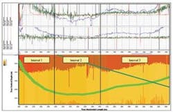
Polar plot views produced while drilling indicate the distance and direction to the nearest boundaries and indicate their dip angle relative to the wellbore trajectory. Using this information, drillers can steer the bit into the highest quality reservoir zones, and avoid hazards, or maintain the hole trajectory a set distance from the reservoir top.
Tough challenges
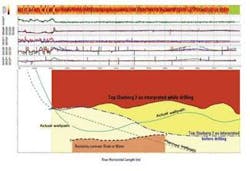
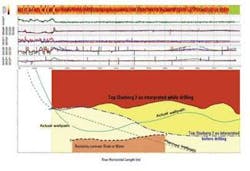
The Oseberg formation, part of the Brent Group, consists of fan delta deposits with thin shale or calcite cemented interbeds associated with clinoform surfaces. The target zone for the first of the two proposed development wells on Veslefrikk was the high net to gross Oseberg 2 Member, a prolific producing bed 131 ft to 180 ft (40 m to 55 m) thick. With large volumes of producible reserves occupying the top of the reservoir and sealed by the overlying shale barrier, the objective was to steer as close as possible to the undulating upper reservoir boundary.
The penalty for a misstep was considerable because the depleted Oseberg 3 Member is just above the thin shale barrier. Drilling into the Oseberg 3 Member could have serious consequences up to and including loss of the well. Other difficulties if the Oseberg 3 Member was penetrated included loss of hole stability, risk of circulation losses, sticking during drilling, and cementing problems. The team decided to attempt a 1,968 ft (600 m) lateral drainhole in the top of the Oseberg 2 Member. With this much reservoir coverage, economic production rates and volumes could be achieved with acceptable drawdown to avoid water coning.
Part of the planning involved building a geological model of the formation. The value of the PeriScope measurement can be seen when actual results are compared with the well plan from the model. As much as 10-15% additional reserves were accessed through use of real-time boundary mapping to geosteer the wellbore over its entire length, avoiding the suspected water level. Among the observations made were the following:
- Well placement was enhanced, and drilling was conducted with confidence without compromising penetration rate
- Precise mapping of the overlying shale surface was achieved
- Directional changes were minimal, leading to a smoother wellbore
- Both upper and lower boundaries could be tracked simultaneously.
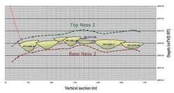
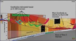
In the second development well, StatoilHydro engineers were confronted with an array of overlapping channel sands in the middle, 33-ft to 50-ft (10-m to 15-m) thick, part of the Ness formation. The objective was to penetrate as many of the channel sands as possible with maximum coverage in each for good productivity. Secondly, if drilling in shale, to be able to detect if an oil-filled channel was above or below the well trajectory.
Timing of drilling information was critical due to proximity of the channels to one another. The directional driller had one chance to make the right steering decision or else miss the target. Interpretation was complicated by the presence of several coal beds.
The wellbore was guided through each pay zone, pausing long enough to take a formation pressure while drilling measurement using the StethoScope formation pressure-while-drilling tool. The pressure measurements confirmed the viability of each channel as a completion candidate. The PeriScope data located the target sands and lead to drilling where they had the highest reservoir quality.
Over the 3,608-ft (1,100-m) track of the second well, 2,788 ft (850 m) of oil-filled reservoir sand was penetrated for 77% coverage. The operator encountered about 30% more channel sandstone than expected from the model, and, compared with conventional geosteering, around 15% more recoverable reserves.
Lessons learned included the following:
- The tool detected and located sand bodies while drilling the shale
- The tool maximized the length it could stay within each channel sand
- The tool enhanced the geological model in a limited area of poor seismic imaging (local peg-leg multiple
- FPWD measurements performed in conjunction with drilling provided important information on reservoir viability and connectivity.
A third development well in this campaign employed conventional geosteering technology to compare and differentiate the results achieved on the other two wells. The operator’s observations from this third well led to the conclusion that the other wells would likely have been unsuccessful had they been drilled using the conventional technology.
SPE paper 95725 was originally presented at the SPE annual conference and exhibition.
