Integrated decommissioning helps meet regulatory and cost-saving targets
Bart Joppe
Ole Petter Nipen
Baker Hughes
Decommissioning is the inevitable final chapter in an operating well's life cycle, in which the well is no longer producing at economically sustainable rates and must be safely and assuredly sealed off to prevent reservoir fluids from migrating across the well or escaping to the surface. In many parts of the world, this process is a regulatory requirement and presents an opportunity for an operator to demonstrate a commitment to being a responsible steward of the environment. However, unlike other stages of the well's life cycle, decommissioning represents a pure cost to the operator and must be completed as efficiently and cost-effectively as possible.
Regulations on P&A operations vary from region to region, but perhaps are most stringent in theNorth Sea. Per regulations set forth by the OSPAR Convention, any operator that drills a well has a legal responsibility to permanently abandon that well once operations are complete. This means removing all subsea architecture—wellheads, templates, manifolds, and pipelines—to leave a clean seabed behind. Because of the higher costs and regulatory requirements in a region such as the Norwegian North Sea, a subsea P&A operation for a single well is a costly endeavor, averaging tens of millions of dollars.
Faced with the dual requirements to permanently plug the well at the lowest cost while also complying with local regulations, operators may benefit from taking an integrated service approach to a P&A job. While many service providers offer one or more P&A services, the ideal solution entails partnering with a service provider that has the depth and breadth of technology and field application experience to deliver and manage all aspects of a P&A operation. An integrated approach helps to simplify management of the project and minimize any risks or delays to keep costs down, meet regulatory requirements, and ensure that the well is securely isolated without the need for subsequent intervention work to plug a leak.
North Sea challenge
Statoil in Norway needed to permanently P&A its field development project that comprised five wells located at 984-ft (300-m) water depth. The wells were tied into a large six-slot subsea template to provide gas and increase production in the nearby field. The subsea installation was 55 m long x 34 m wide x 13 m tall (180 ft long x 112 ft x 43 ft).
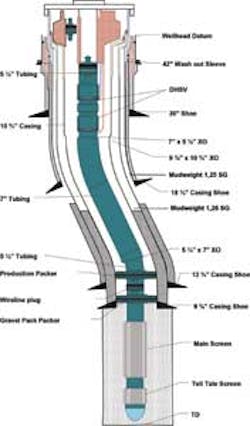
Between 1991 and 2002, Statoil estimates that roughly 21.7 bcm (766 bcf) of gas was injected into the field, resulting in increased total production of 65-125 MMbbl of oil. In 2011, the operator decided to idle and temporarily abandon the wells by removing the subsea trees and setting plugs to prevent cross flow and keep reservoir fluids contained. By 2012, the decision was made to permanently decommission the development. The scope and difficulty of the P&A project were considerable. The project would require establishing a deep well barrier, followed by cutting and pulling the 95⁄8-in. x 10¾-in. and 133⁄8-in. casing, 18¾-in. wellhead, 30-in. conductor, and 42-in. washout sleeve. All wells needed to be disconnected from the subsea template by cuts below the seabed.
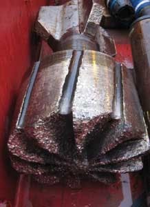
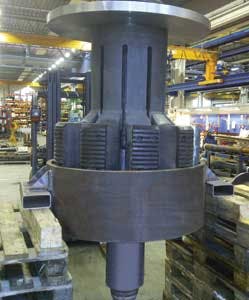
Statoil contacted Baker Hughes for assistance. After carefully reviewing the job details and developing a plan of execution with the operator's project coordinators from the field, the service company deployed teams to provide a coordinated effort that included cementing services, fluids, mud logging, milling, cutting, and fishing services. Preplanning discussions uncovered the need for a number of specialized, nonstandard tools for the project, including large-size cement mills, casing cutters, and casing spears.
Planning includes contingencies
With the semisubmersible rig in place above the wells, Baker Hughes commenced operations by pulling the completion for the first of the five wells. This was a relatively straightforward process that involved first deploying a tubing hanger running tool, picking up the tubing, and pulling it out of the hole.
A logging tool was then deployed via electric wireline to find the correct placement for the cement barrier and to identify gas below casing hanger. Once the proper barrier location was identified, cement plugs were placed in the 95⁄8-in. casing to satisfy NORSOK Standard D-010 requirements of having well barrier elements across a total of 330 ft (100 m).
For removing the 95⁄8-in. x 10¾-in. casing, first a shallow cut inside the 10¾-in. casing was made using a multi-string cutter to verify no gas was trapped below the casing hanger. Prior to pulling the cut casing out of hole, the P&A team noticed that the casing hanger was stuck. A contingency had been set up for this possibility during the planning stages, which called for milling out the seal assembly on the 10¾-in. casing hanger using a specialized 185⁄8-in. junk mill. Once this was successfully milled, the 95⁄8-in. x 10¾-in. casing strings were cut deeper and retrieved using a type-B spear.
Proper planning with the operator helped ensure that the casing could be cut and pulled in one run with the spear, mud motor, and cutter assembly all deployed downhole during the same run. This reduced the number of trips downhole, which reduced non-productive time and saved on rig costs.
Operations then shifted to the upper wellbore P&A, in which a cement plug was first set inside the 133⁄8-in. casing. The casing was cut and the seal assembly was milled out using the junk mill, similar to the process used for the 10¾-in. casing hanger. The cut 133⁄8-in. casing section was then pulled using a Model B spear.
A total of 16 cut-and-pull operations were performed on all five wells to remove the 95⁄8-in. x 10¾-in. and 133⁄8-in. casing. The spear and motor were combined on eight of the trips to reduce the total number of trips and maximize efficiency.
The 18¾-in. wellhead was the next piece of equipment to be removed. The wellhead was connected to the 30-in. conductor by spring-loaded pins, so more than 136 tons of overpull was applied to shear the pins and pull the wellhead free. After the wellhead was cut using a casing cutter, the company's Model D spear with jars and accelerator was used to jar the wellhead free.
Next, the spring-loaded pins that attached the 30-in. conductor to the template were sheared, and a dedicated run was made to cut the conductor. Cutting depth was 3.2 ft (1 m) shallower than the cut in the 18¾-in. wellhead. The 30-in. conductor was then jarred free using a 20-in. type-D spear. A cement cleanup run using 333⁄8-in. and 45-in. cement mills was then made down to the top of the conductor cut, and to the top of the 42-in. washout sleeve.
Finally, the 42-in. washout sleeve was cut using a modified cutter, which was centralized inside the washout sleeve. A custom type-E spear was deployed to successfully pull the 42-in. washout sleeve free. Twenty-five runs were made to cut and pull the wellhead, conductor, and washout sleeve.
At the conclusion of the job, all five wells were permanently plugged, all wellheads and conductors were pulled free from the template, and the template was lifted away from the field.
Conclusions
The integration of P&A services and the close collaboration with Statoil ensured maximum efficiency and reduced HSE risk. By combining cutting and pulling operations in several of the runs, the operator reduced rig time, an important priority given the average day rate of $500,000 for semisubmersibles in the North Sea.
According to some industry estimates, up to 1,200 wells will have to be decommissioned in Norway over the next 20 years. To deal with this sizable scope of work, operators will continue to look for ways to make the P&A process as safe, fast, and inexpensive as possible. An integrated P&A approach shows great promise in meeting these objectives.
