Deepwater isolation, shallow-water flow hazards test cement in Marco Polo
New slurries help reduce the known risks
Eric Kolstad
Anadarko Petroleum
Greg Mozill
Juan Carlos Flores
Schlumberger
Cement integrity achieved in the Gulf of Mexico Marco Polo development in Green Canyon block 608 is putting innovative slurry systems on the map of sought-after technologies for deep-water plays. These new slurries help reduce the known risk of shallow flow and combat possible formation of gas hydrates.
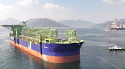
While Anadarko considered conventional foamed slurries in the planning phase of this 20-in. conductor at 4,000 ft below the mudline in 4,300 ft water depth, new cementing technologies were selected to heighten certainty of cement integrity in the presence of hazards prevalent in the deepwater GoM. The Marco Polo development, currently the deepest commercial play for Anadarko, is 150 mi from the Louisiana coast.
To date, six 20-in. surface and six, 9 5/8-in. production casing strings have been cemented. The cements were mixed on the fly with no placement problems and no flows after cementing, and leakoff tests have been better than anticipated.
Advanced flexible cement
Selection of Schlumberger DeepCRETE deepwater cementing slurry over the predominate foamed cement for the six 20-in. surface casing strings saved Anadarko about $600,000 on the exploratory well and subsequent development wells cemented as a group. The six 9 5/8-in. production casing strings cemented with FlexSTONE advanced flexible cement technology allowed Anadarko to pocket approximately $250,000 needed for a proposed study to determine if the production strings on these wells would collapse or lose integrity if conventional systems were used. Because it exhibits properties greater than that of conventional foamed and chemically extended cements, Anardarko opted to use conventionally mixed FlexSTONE optimized particle size distribution (OPSD) slurry.
null
The presence of overpressured shallow sediments in the deep-water GoM has led to numerous drilling and cementing problems. These overpressured zones are prone to uncontrolled flows of massive amounts of saltwater or gas, especially after cementing operations. Uncontrolled flows from such sands have led to total loss of the well in several cases.
Cold temperatures at these depths have an adverse effect on fluid viscosity and setting time for cement, and increase the tendency of gas hydrates to be created as a result of cement hydration and the presence of shallow gas. A narrow margin also exists between pore and frac pressures, resulting in lost returns during cement operations.
As surface casing shoes are being pushed deeper below the mudline and production casing integrity becomes even more crucial, new slurry designs offer viable and economically attractive solutions, addressing the effects of low temperatures and shallow gas by remaining flexible to shrinkage and wellbore stress changes and by creating a reliable bond at the cement-rock and casing-cement contacts.
The deepwater distinction
There are four areas of differentiation for cementing at great depths: cost, cold temperatures, narrow pore and frac pressure margins, and shallow water-gas flow hazards.
Cementing operations take longer in deep water, and rig time represents a significant expense.
The temperature at the seafloor will range from 35° F to 45° F, and the bottomhole static temperature may be as low as 50° F. The density of the lead cement system will be in the range of 11-13 lb/gal due to low fracture gradients. Many of the required hydraulic and mechanical properties are very difficult to achieve under such conditions. Low temperatures affect fluid viscosity, setting time, and gel strength development of the slurry.
The narrow margin between pore and frac pressures not only causes lost returns during cementing, but also leads to lost circulation during drilling. Studies have shown that a minimum increase of 10% in density for each successive fluid is ideal for effective displacement of one fluid by another in an annulus. The narrow pore and frac pressure margins make this density hierarchy difficult to achieve.
Geohazards – shallow saltwater flow and gas hydrates – present the greatest challenge in the deepwater cementing equation. Shallow-water flow is created by permeable sediments, such as a turbidite sand, trapped under sliding deposits and is typically found at the mouth of major rivers. Areas where shallow saltwater flows have been encountered in the GoM are primarily on the transitional slope between the continental shelf and the deep abyssal environment in water depths ranging from 1,000 to 7,000 ft, although isolated flows have been reported in water as shallow as 500 ft. Shallow flow can cause safety and environmental concerns, flow during drilling or cementing that can jeopardize template stability, and lost circulation during drilling or cement placement which affects well control. It can also cause excessive hole washouts that make mud removal difficult, destabilization of near-wellbore formations that compromises the integrity of the BOP and riser, and breakthrough of the seafloor, resulting in loss of drive pipe, conductor, or the well.
The integrity of the seal at the conductor casing seat is probably the most important link in controlling shallow flows. A competent seal will keep any unwanted flow on the inside of the pipe, greatly improving the chances that it can be successfully killed. If the flow is allowed to breach this casing seat and reach the surface behind the pipe, the well will likely be lost. It is also important to have good cement behind the pipe from the shoe to the mudline to circumvent casing buckling and wear problems that eventually compromise the well stability.
null
Gas hydrates
Gas hydrates are solid, ice-like compounds formed by natural gas and water in high-pressure, low-temperature environments. One unit of gas hydrate is the equivalent of 170 units of gas, and the formation of these hydrates represents a major blowout hazard. In the GoM, they exist near the seabed where destabilization is an issue, and shallow gas can form in the well and in the pipes.
Gas hydrates can destabilize as a result of heat generated from the drill fluid or during cement hydration. During cementation, contributing factors to the creation of gas hydrates include the total heat released during the hydration process, heat flow, and dissipation flow. Form-ation of gas hydrates plugs of the BOP choke and kill lines, dehydrates drill fluids or cement, and overloads of gas separation equipment. To further complicate matters, logistical, economical and environmental requirements must also be met.
Cementing objectives
The objectives for cementing in shallow flow areas are threefold: (1) to achieve a competent hy-draulic seal that will not allow migration of fluids, especially salt-water flows, behind the pipe, (2) to give structural support to the pipe so that it will resist buckling and casing wear, and (3) to provide long-term durability for the life of the well.
Both the conductor and surface casings are cemented via an inner string of drill pipe. This minimizes displacement volumes, minimizes cement contamination, and minimizes the amount of seawater that must be circulated from the inside of the pipe once the casing has been landed. The casing is hung off at the mudline, and returns are taken through cementing ports at the seafloor. Alternatively, the surface pipe may be cemented with a riser in place so that returns are to the rig floor.
To improve the chances of a successful cement job, it is critical that the well be static prior to and during cementing. The kill mud in the hole must be the proper density to control saltwater flows without breaking down the weak, unconsolidated sediments.
Influences on selection
In deepwater, good mechanical properties do not equal good slurry properties. Conven-tional cement slurries are not applicable because the water needed for conveyance also results in longer working time, lower compressive strength and higher permeability.
null
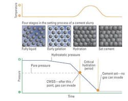
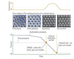
Until now, compressible cements were used to control flows. In theory, the compressed gas in the cement will maintain a matrix pressure in the slurry above the pore pressure of the flowing zone as the cement undergoes the critical hydration period (CHP). The large volume of gas in the slurry will also help to compensate for slurry volume reductions due to fluid loss and volumetric shrinkage. Historically, the compressible cements that have been used for gas migration control are either foamed cements or in-situ gas-generated cements.
Although foamed cements had been used successfully on other projects, Anadarko sought simpler, safer, and less expensive alternatives. Like foamed slurries, the new OPSD slurry designs are capable of handling shallow flow potential and contain chemicals to facilitate gas blocking and rapid gel strength development. Unlike foamed slurries, the OPSD slurries operate at one-half the concentration and without the need of nitrogen pumping equipment and personnel. Costs are reduced, and associated safety and environmental risks are mitigated.
System design
Cementing in deepwater shallow-flow areas requires special attention to cement system design, particularly for the lead cement. The cement slurry must exhibit certain hydraulic properties for proper placement in the wellbore while the set cement sheath must possess certain mechanical properties for long-term zonal isolation and structural support. In the fluid state, consideration must be given to stability, fluid loss, rheology, thickening time, and CHP. Once the cement is set, acceptable compressive strength, permeability, shear bond strength, and ductility are required.
null
Slurry stability
Required slurry stability is defined by zero free water and no significant settling or sedimentation. If the slurry has excessive free water, channels will form that may result in a loss of zonal isolation. Free water will also lead to a slurry volume reduction. As water is removed from the slurry, a pressure drop in the cement column can lead to an influx of reservoir fluids. Settling will also cause density differentials that may result in insufficient hydrostatic pressure to maintain well control.
By virtue of adaptability, recently developed OPSD slurries exhibit superior set cement properties that can stand cyclical stress variations, good bonding to the casing and formation, and with the addition of additives prevent gas migration in the setting slurry.
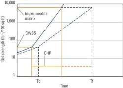
Innovative development in the DeepCRETE slurry for deepwater has exhibited low density, excellent fluid loss control, no free water or sedimentation, rapid waiting-on-cement time at low temperature, and a shortened critical hydration period (from 0 to 45 minutes) in which a lab test result from the Marco Polo development showed 17 minutes.
Flow regimes
Effective displacement criteria can only be met if the fluids are carefully designed with respect to rheological properties and des-igned annular flow rates are met. Rheologi-cal properties must be suitable for proper annular fluid displacement, meaning the lead slurry must generate a friction pressure greater than that of the spacer and less than that of the tail slurry.
Fluid loss
Fluid loss control, both dynamic and static, is an essential property. When excessive amounts of fluid are lost from the slurry during placement, there are numerous consequences. Dynamic fluid loss will result in an increase in slurry density that may result in lost circulation. Also, if a significant percentage of water is lost from the slurry, other properties such as rheology and thickening time may be adversely affected. Static fluid loss, if not carefully controlled, will lead to a slurry volume reduction and can allow reservoir fluids to enter the slurry. Premature setting of the cement in the inner string and possibly even in the cementing unit becomes a definite risk.
Compressive strength
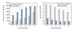
The set cement must develop adequate mechanical properties to support the casing for the life of the well. Obtaining the generally accepted compressive strength on the order of 500 psi in 24 hours at borehole static temperature requires custom cement blends at the densities and temperatures encountered. Compressive strength of the Marco Polo cement system was ~14 hours to 500 psi.
Permeability
While the low-density property addresses the seal requirement, migration of reservoir fluids into the unset slurry may form secondary flow paths that effectively increase the matrix permeability of the set cement. Resistance to the generation of this secondary permeability in low-density cement systems is achieved by adding very fine particulate material to the mixture. These materials act to plug pore throats and reduce permeability of both the cement slurry and set cement.
Critical hydration period
The CHP is a period of time that begins when the slurry no longer transmits hydrostatic pressure that overbalances the pore pressure of the formation and ends when the slurry has developed enough cohesive strength to prevent the entry and flow of reservoir fluids into the annulus. The new slurry designs exhibit a greatly reduced CHP through rapidly increased gel strength development, such as the 17-minute CHP for the DeepCRETE slurry system.
