The benefits of light annular mudcap drilling in naturally fractured formations
C.R. Stone
George Medley
Signa Engineering Corp.
Since the onset of rotary drilling, encountering fractured formations has plagued drillers due to severe lost circulation and hydrocarbon influx into the wellbore during operations. Drillers have also experienced complex and hazardous well-control situations while drilling in high-pressure formations containing multiple fractures.
Admittedly, such formations are a mixed blessing. Many operators target reservoirs that have extensive natural fracturing because of the prolific production associated with fracture porosity. So, it is not desirable to permanently plug any hydrocarbon-bearing fractures.
In the past, many conventional methods have been used to combat the problem of lost circulation, such as using lost circulation material (LCM), or "drilling blind" to subsequently set casing across the loss zone.
However, a number of today's developing oil fields have been found to resist the efforts of such conventional methods – in particular, sour, high-pressure fractured carbonate reservoirs in Kazakhstan, South America and other regions of the world.
The development of light annular mudcap drilling (LAMCD) has tackled some of the problems associated with the hazards and production losses encountered while drilling in fractured formations.
LAMCD is a safe, cost-effective drilling technique that can prove fruitful when drilling through massively fractured formations or where karsts are prevalent, especially when productive fluids are sour. A karst is a distinctive topography in which the landscape is largely shaped by the dissolving action of water on carbonate bedrock (usually limestone, dolomite, or marble). This geological process, occurring over many thousands of years, results in unusual surface and subsurface features ranging from sinkholes, vertical shafts, disappearing streams, and springs, to complex underground drainage systems and caves.
null
The LAMCD technique allows the driller to control and monitor the amount of sour gas migrating into the annulus.
LAMCD technique
So called because of the lower-density viscous fluid used in the process, the LAMCD technique allows the driller to control and monitor the amount of sour gas migrating into the annulus.
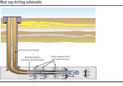
During drilling, the choke is completely closed. At the same time, a rotating control device (RCD) is used to seal the annulus.
A sacrificial fluid (usually fresh or brine water) is injected down the drill pipe while drilled cuttings are transported up and deposited into vugs or fractures above the bit. (Vugs are natural cavities formed in certain formations due to leaching out of soluble materials. These cavities are lined with a crystalline material and a composition different from that of the surrounding area. The size of a vug may vary from a small pea to a large boulder.)
The annulus is periodically injected with a viscous fluid, which has a density slightly less than the pore pressure equivalent – hence the name, light annular mudcap drilling.
null
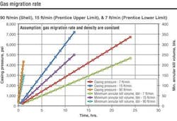
The casing pressure increases as hydrocarbons migrate up the annulus. The value of the casing pressure qualitatively corresponds to the height of the hydrocarbon migration.
Once a pre-determined casing pressure is reached, a specialized LAMCD fluid is pumped into the annulus until all the hydrocarbons are displaced back into the formation. After all the hydrocarbons are purged from the well bore, the casing pressure safely returns to a constant and predictable value.
This controlled displacement process results in a predictable positive casing pressure in formations where conventional drilling methods might not be possible or economical.
In essence, the LAMCD technique allows an operator to continue drilling through fractures or faults to total depth with reduced trouble time and cost, while minimizing mud losses to the formation.
Evolution of the process
The LAMCD technique is actually an adaptation of regular mud cap drilling (MCD). Regular MCD is a form of "blind drilling" that evolved during the exploitation of the Austin Chalk in Texas and Louisiana.
In the Austin Chalk formation, specifically in the Pearsall Field, cross flow (from pressured fractures to depleted fractures) caused costly fluid losses and dangerously high surface pressures.
Drillers, who were using the flow drilling technique at the time, began pumping water down the annulus while injecting down the drill pipe to bring annular pressures below the operating limit of the RCD. As drilling continued and the trend was exploited further, MCD began to evolve.
Drillers pumped a weighted viscous mud down the annulus with the choke closed. At the same time, water was pumped down the drill pipe and into the fractures to prevent hydrocarbon migration to the surface and subsequent high pressures. This "pressurized mudcap" allowed drillers to continue with lower annular pressures.
Signa Engineering Corp.'s LAMCD technique – as it is performed in the Austin Chalk and other sweet formations – differs slightly from regular MCD. The LAMCD method allows monitoring of sour gas migration in the annulus; with the original MCD technique, the rate of migration was uncertain.
The mudcap fluid used in MCD has a slightly higher density than the pore pressure equivalent (0.2 – 0.4 ppg greater). LAMCD uses a mud that is slightly less dense than the pore pressure (usually 0.1 – 0.3 ppg less).
Mudcap drilling has been shown several times to be a safe and economical alternative to conventional underbalanced drilling. Some areas where MCD has been used successfully include:
- Bashkirian formation, Kazakhstan. Sour gas present.
- Buda formation, Texas/Louisiana. No sour gas.
- Georgetown formation, Texas/Louisiana. No sour gas.
- Glenn Rose formation, Gulf Coast. No sour gas.
- Mission Canyon formation, Williston. Sour gas present.
- Limestone formation, Middle East. No sour gas.
- Cogollo formation, Colombia/Venezuela. Sour gas present.
- Carbonate Structures formation, Sarawak. Sour gas present.
null
Bashkirian Formation
The LAMCD technique's safe and efficient methods were proven indispensable during the drilling of the Bashkirian formation in Kazakhstan.
While drilling a sour, high-pressure fractured reservoir on the northeastern edge of the Caspian Sea, drillers encountered a challenging obstacle: the formation was riddled with multiple fractures, resulting in severe lost circulation while drilling, followed by hydrocarbon gas influx into the well-bore.
The reservoir in question was formed during Devonian and Carboniferous geological time by recurrent deposition of skeletal fragments along with lime mud (where karsts are frequently encountered).
The top of the reservoir is below 12,600 ft in one particular area that was temporarily suspended. Drillers encountered severe problems while drilling the pay horizon below approximately 13,100 ft in that specific area.
Lost circulation had been a consistent problem for drilling operations since the discovery of the field, ranging from minor issues to catastrophic losses (drilling fluid losses of 800 bbl/hr had been encountered while drilling with as little as 0.3-ppg overbalance).
Lost circulation was frequently encountered over the entire field, but was especially predominant at the reservoir in question. Conventional remedies and techniques had been exhausted; some with varying degrees of success – but none completely remedied the situation.
After drillers found little or no success in the tiring implementation of those tactics (along with the costly amount of lost product), it was obvious a change was needed.
Engineers began to pursue alternatives, and soon initiated the LAMCD technique at the reservoir.
The successful application of LAMCD resulted in the first complete penetration of the reservoir without severe whole mud losses. After all of the reservoir fractures had been penetrated, a liner was installed to isolate the fractures using the same mudcap well-control procedures employed while drilling the interval.
The success of the LAMCD technique in Kazakhstan, along with its implementation in many other parts of the world, shows that the technique can solve many lost circulation and well-control problems associated with drilling in highly fractured formations.
Annular fluid density
The first step in successful implementation of LAMCD is determination of annular fluid density.
The troublesome Bashkirian well that was just discussed was predicted to have a pore pressure equivalent mud weight regression from 15.8 ppg at the top of the reservoir (at approximately 13,150 ft), to 14.2 ppg at the bottom of the reservoir (at approximately 15,400 ft).
The ideal formation for the LAMCD technique is one that has low injectivity pressure into the formation or, conversely, high conductivity from the formation. In other words, the imposed pressure to pump into the formation after encountering a fracture may be as little as 10 psi.
As was previously stated, LAMCD is best applied in situations where natural fractures or karsts exhibit severe loss of circulation during drilling. The desirability of the technique is also increased where there are high bottom-hole pressures and high bottom-hole temperatures and where there are H2S-bearing hydrocarbons. So, the task of determining the annular fluid density must be specific. The data collected is used to determine the mud density for a certain portion of the hole.
Typically, in conventional types of drilling, the pore pressure of the formation that is being drilled is already known from offset data or can be "guesstimated" within a certain degree of accuracy.
In LAMCD, that is not the case. The pore pressure must be determined as accurately as possible to ensure the success of the technique's ability to displace any migrated hydrocarbons back into the formation.
In the field, drillers have a proven method of determining pore pressure: First, they prepare a trip tank with "cutback fluid." This fluid is used to chase the falling mud column when drillers encounter a formation that causes complete loss of circulation.
When the loss of returns is noted, the team fills the annulus with cutback fluid until the well-bore remains full.
Then, they close the annulus and wait for the casing pressure to stabilize. Using the known mud weight in the hole at the time of the loss, plus the hydrostatic weight of the cutback fluid combined with the annular pressure, the pore pressure can be accurately determined (if the affect of the cuttings on density is neglected).
Closing the annulus when the fluid first fills the hole will minimize influx (unknown density) and allow the casing pressure to give a closer approximation of the actual downhole pressure.
Injection pressures
For planning purposes, standpipe pressure can be estimated for drilling in both static and dynamic conditions. The following equation is used for static standpipe pressures:
PSPPstatic =
0.052 * (EMWpp - MW drill pipe) * TVD
where, PSPPstatic is the static standpipe pressure, which is the U-Tube pressure imbalance between the drillpipe and the exposed formation pressure.
The dynamic or standpipe injection pressure is equal to the static standpipe pressure plus the pressure losses down the drill string and into the fractures.
If mudcap drilling is attempted in the presence of very small-volume fractures, pressures may increase beyond the pressure rating of the mud pump pressure.
Injection volumes
Whether drilling with or without a down-hole motor, injection volumes required for MCD can be easily estimated.
The injection rate for drilling without a motor will depend on the drilling conditions.
Typically, the injection rate should be (at least) the normal circulation rate used to remove cuttings when drilling with water. The minimum annular velocity to remove cuttings from a vertical well with water is estimated to be 100-150 ft/min.
However, that estimation should be used to determine the minimum fluid needed, as some hole conditions may require higher annular velocities due to uneven injection of fluid into or along the well-bore.
When using a motor down-hole, the injection volume is dictated by the volume requirement for the motor. Resulting annular velocities are normally much greater than the minimum velocity required for efficient removal or injection of cuttings.
For example: a 4 3/4-in. mud motor requires about 240 gpm to operate. This equates to an annular velocity of 233 ft/min when using 3 1/2-in. drill pipe in a 6-1/8-in. hole. The respective volume requirement is 6,171 bbl for an 18-hour circulating day.
Whether using periodic, continuous, or random annular injection, the annular injection volume and the respective daily volume can be estimated by using a set of equations.
Equipment needed
Compared to other types of underbalanced drilling, little equipment is needed for the MCD process, giving MCD a major advantage over other types of underbalanced drilling in the equipment arena.
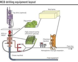
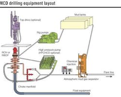
MCD requires two types of equipment: surface and down-hole. Surface equipment can be divided into the following categories – BOP equipment, contingency gas separation equipment, and circulating equipment.
Basically, the type of blowout preventer equipment (BOPE) required for MCD is the same as conventional drilling, with the addition of a rotating control device (RCD) installed on top of the stack.
However, high-pressure mudcap drilling (HPMCD) calls for an additional high-pressure circulating system, including cement- or fracture stimulation-type pumps.
Since most LAMC drilling is done in high-pressure reservoirs, high-pressure surface equipment is often used in the technique.
It is not always necessary (nor practical) to rate the RCD for the maximum allowable surface pressure.
The RCD is used to seal the annulus while still allowing rotation and hole movement of the drill pipe. If surface pressure approaches the rating of the RCD, the pipe rams are usually closed and annular fluid is injected into the annulus until surface pressure comes within an acceptable range.
Note: The RCD is the last barrier between pressurized well-bore fluids and drilling rig personnel, so the RCD should never be used as a shut-in device (regardless of its pressure rating).
In LAMCD operations, it is important that all inside-pipe shutoff tools be used, or at least available, during operations. This will assist in containing abnormally high injection pressures that may be present due to an unbalanced "U-Tube" environment.
Tandem drill pipe floats should be placed inside a bit sub-bored for tandem floats – a piston or "flapper-type" float valve is typically used. In extreme high-pressure MCD (with standpipe pressure greater than 5,000 psi), a high -pressure differential float valve can be installed above the tandem float valves for added safety and redundancy.
Since the annulus is sealed, preventing fluids from returning to the surface, gas separation equipment is not normally used in MCD operations. However, it is a good idea to have the equipment readily available in the event the annulus is opened.
If using one, a mud gas separator or gas buster should be placed downstream of the choke so that large volumes of gas can be routed away from the rig through a flare line.
Circulating system
All the components of the circulating system – rig pumps, manifolding, check valves, Kelly hose, standpipe and the drillstring – must be able to withstand the injection pressure while mudcap drilling. Double or redundant check valves should be placed between the pump discharge and the standpipe and casing valves.
A minimum of two rig pumps should be manifolded so that water (or mud) can be pumped with either pump down the standpipe or the annulus. If offshore work is being done, high-pressure cement pumps should be manifolded for pumping from the pits down the standpipe or the casing.
Emergency shutdown switches for any high-pressure pumps should be placed strategically around the rig for safety, and a third party should check the manifolding to guarantee safety.
Standpipe
Most drilling rigs have a standpipe rated for 5,000 psi working pressure, and in turn all of the valves and fittings should be rated (at least) comparable to the standpipe rating.
Many rigs, particularly offshore, have two standpipes. In this case, the standpipe manifold should contain a valve or a block placed in the crossover line to separate the top-drive bleed-off line from the second standpipe that will be used for pumping down the annulus.
Each standpipe should also have a Kelly hose attached, one being the active standpipe and the other a standby. An air-actuated bleed-off valve should be installed to allow the driller to safely bleed off the pressure at the standpipe from the driller's console (instead of from the standpipe manifold).
The standard rotary hose(s) is actually 3-in. ID rated for 7,500-psi test and 5,000-psi working pressure. If the rig has two standpipes and Kelly hoses, both hoses should be tested to their full pressure during blowout preventer tests.
Swivel drives, or "top drives," are recommended highly for MCD because of pipe movement/rotation abilities and monitoring. They should have a minimum pressure rating the same as the standpipe and rotary hose.
References
1. Colbert, John W., SPE and Medley, George, SPE, "Light Annular MudCap Drilling - A Well Control Technique for Naturally Fractured Formations," Copyright 2002, SPE. Paper was selected for presentation at SPE Annual Technical Conference held in San Antonio Texas, Sept. 29 - Oct. 2.
2. Urselmann, R. et al: "Pressured MudCap Drilling: Efficient Drilling of High-Pressure Fractured Reservoirs" Paper SPE/IADC 52828 presented at the 1999 SPE IADC Drilling Conference held in Amsterdam.
3. Johnson, J. et al: "High Efficiency Drilling - a Novel Approach for Improved Horizontal and Lateral Drilling," Paper SPE 52185 presented at the 1999 Mid-Continent Operations Symposium held in Oklahoma City, Oklahoma.
4. Reyna, K.: "Case History of Floating MudCap Drilling Techniques - Ardalin Field, Timan Pechora Basin, Russia," Paper, SPE/29423 presented at the 1995 SPE/IADC Drilling Conference held in Amsterdam.
5. Berger, Bill D. and Anderson, Kenneth E., "Modern Petroleum: A Basic Primer of the Industry," a broad overview of the upstream and downstream of the industry. Copyright PennWell Books, Tulsa, Oklahoma.
6. Kennedy, John L., "Fundamentals of Drilling: Technology and Economics," Copyright PennWell Publishing Company, Tulsa, Oklahoma. A general study of the diverse skills and basic drilling procedures that make up the industry.
7. Sweep, M.N., ChevronTexaco Exploration & Production Technology Company; Bailey, J.M., ChevronTexaco Overseas Petroleum Inc., Tengizchevroil, LLC; Stone, C.R., Signa Engineering Corp., "Closed Hole Circulation Drilling: Case Study of Drilling a High-Pressure Fractured Reservoir - Tengiz Field, Tengiz, Republic of Kazakhstan," Copyright 2003, SPE/IADC Drilling Conference.
Authors
C.R. Stone, P.E. Rick Stone is the chairman and CEO of Signa Engineering Corp. in Houston, Texas. Rick has over 23 years' experience in oil and gas operations. A longtime member of SPE, Rick has served the society as a Distinguished Lecturer. Rick received the SPE Drilling Engineer of the Year Award from SPE President Andrew Young at the 2003 conference. He is a member of IADC and UB Advisor - IADC Wellcap Committee. Rick holds a Bachelor of Science degree in mechanical engineering from Texas A&M University. He can be reached at [email protected].
George H. Medley P.E. George Medley is the executive vice-president of Signa Engineering Corp. with over 26 years in oil and gas operations and R&D. Along with extensive drilling, completion, and operations management, he has managed major R&D projects for the US Department of Energy, the Gas Research Institute, and the Drilling Engineering Association. He has developed multiple training courses in unconventional drilling techniques. George holds a Bachelor of Science degree in civil engineering (Summa Cum Laude) from Texas A&M University. He can be reached at [email protected].
