Offsets, mooring, safety critical to operation
Jennifer Tule, Hans Treu, Tom FultonThe following article is a summary of a technical paper entitled "Pushing the Potential - Drilling Additional Wells in the Existing Pattern From a MODU with the Neptune Spar Offset," by Don Vardeman of Oryx and Roger Glanville of Deep Oil Tech nology to be presented at the Deep Offshore Technology Conference, November 17-19, 1998 in New Orleans.1098offaker1.jpg
Aker Marine Contractors
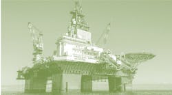
The Ocean Lexington moored alongside the Neptune Spar.Last year, Aker Marine Contractors was asked by Oryx Energy Company and partner CNG Producing to develop solutions for mooring a semisubmersible drilling unit adjacent to the Neptune Spar Platform, located in Viosca Knoll Block 826 in the Gulf of Mexico.
The purposed of the unit was to drill additional wells beneath the Spar platform. Currently, seven wells are producing on the Spar platform. The Spar is a floating production facility moored to the seafloor by six taut leg mooring lines in 1,930-ft water depth. Each mooring leg consists of a driven anchor pile, sections of chain, and jacketed spiral strand wire.
Since the Spar cannot support a full drilling rig, the unit's mooring system and riser systems were designed to allow the Spar to offset 250 ft to the northeast or southwest in order to make room for a mobile offshore drilling unit (MODU). Mooring a MODU in a safe manner would require presetting a special mooring system, moving the Spar to the northeast or southwest on its own moorings, and hooking up the MODU to the preset moorings.
Earlier this year, Oryx decided the MODU would drill additional wells in the northeast row of wells with the MODU moored over the wells, and the Spar offset 250 ft to the southwest. Initially, several types of semisubmersible MODU's were considered for this work. Diamond Offshore Drilling's Ocean Lexington was selected for the project. This rig was capable of drilling in this water depth, and its dimensions provided acceptable clearances from the Spar platform.
Due to the critical nature of the side-by-side operations, it was decided that the MODU would not be moored alongside the Spar during the height of the hurricane season. The time frame selected was from early-1998 to mid-July 1998. However, the mooring system was designed to survive a 10-year hurricane. In the event a potentially larger hurricane might enter the Gulf before mid-July, drilling operations would be suspended, the MODU disconnected from its moorings, and towed to separate survival location.
Aker Marine Contractors (AMC) was responsible for the mooring system design, development of mooring procedures, supply of all mooring components, providing anchor handling crews, management of all mooring installation work in the field, and all field engineering. Diamond Offshore Drilling and Oryx were consulted during all phases of the project.
The Ocean Lexington was successfully and safely moored and un-moored alongside the Spar, and the rig was able to perform the drilling operations effectively.
Design and engineering
In addition to the 10-year hurricane criteria (survival condition), the mooring system was also designed to withstand 1-year wind dominant winter storm conditions (operating condition), and a 10-year site specific wind dominant winter storm (standby condition). Each condition required a different MODU position relative to the Spar. In the operating condition, the MODU must maintain position over the wells with the riser attached, while maintaining adequate clearance from the Spar.When maximum drilling conditions are reached, as measured by mooring line tensions, or based on weather forecasts, the MODU was required to move 150 ft away from the Spar to the standby position, with the riser still connected. For those weather conditions predicted to exceed the 10-year winter storm conditions, the drilling riser would be disconnected and the MODU moved to the survival position, at 500 ft to the NE of the Spar, while the Spar would be moved back to its own mooring center.
The MODU mooring system was designed to API RP 2SK Recommended Practice and to DNV POSMOOR Rules. DNV rules were used in the mooring design, due to the fact that they are more specific and more stringent for MODU moorings alongside a platform. DNV rules require a minimum factor of safety of 3.0 in mooring lines keeping the MODU away from the Spar, and a minimum factor of safety of 2.7 in lines keeping the MODU toward the Spar. DNV also requires that a minimum clearance of 33 ft be maintained between the MODU and the Spar during transient motions following a one-line failure.
Mooring design
Early in the mooring design process several types of MODUs were considered to determine the impact of their physical dimensions, motions, and mooring pattern on the clearance between the Spar and the MODU, and between the two mooring systems. It was determined that the Ocean Lexington was available and a suitable candidate for this operation. The Ocean Lexington is a Zapata SS-2000 design semisubmersible drilling rig with six columns and eight mooring lines.The mooring system was designed using the program GMOOR. In addition the program Mimosa was used to analyze MODU transient motions, and to verify GMOOR results. AMC's in-house catenary shape program QMOOR was also used to analyze complex mooring line shapes for mooring line clearance checks during operation and installation phases such as hookup and disconnect operations.
It was determined that a mooring system composed of 12-ton high holding power (HHP) drag embedment anchors, 3-in. anchor chains, 3-in. wires, with a 50-kip submersible buoy in each leg, could maintain the MODU at safe distances from the Spar in the different environmental conditions. In the operating condition, the clearance between the Spar and the MODU was approximately 100 ft. The MODU used its own mooring wire to connect to the preset system. However, to meet DNV safety factors the existing 2-3/4-in. rig wire was replaced with new and higher strength wires.
In addition to the minimum 33-ft clearance between the platforms, the clearances between the mooring lines of the MODU and the Spar were analyzed carefully. AMC designed the MODU mooring lines to remain above the Spar mooring lines with a minimum clearance of 100 ft. This minimum clearance was applied to all installation, removal, drilling, standby, and survival conditions.
In the operating, standby, and survival conditions, the clearance between the mooring lines was found to be at least 300 ft. However, during hookup and disconnect of the mooring lines the clearance was as small as 140 ft for the most critical MODU mooring legs.
Operations engineering
The mooring legs were pre-installed using anchor handling tug supply (AHTS) vessels. Each preset mooring leg consisted of a drag embedment anchor, ground chain, two sections of wire, and a 50-kips net buoyancy submersible buoy. Special care was given to the placement of each anchor since old wells, export pipelines, and Spar mooring legs existed in the area.Each preset mooring leg was loaded by the AHTS to approximately 50 tons bollard pull to ensure the anchor was embedding properly. Each preset mooring leg was buoyed off using the 50-kip buoy until the MODU was ready to be connected.
Preset hookup
Since all but one of the mooring lines cross at least one of the Spar mooring legs, special consideration was given to the connection sequence of the mooring legs to the MODU. Three towing vessels were used to tow the MODU on site and help maintain position during the hookup of the first four mooring legs.The MODU was positioned at the 500 ft offset location for the hookup, while the Spar was already moved to the 250-ft SW offset, in order to provide the towing vessels and hook-up vessel with adequate maneuvering room.
To connect the MODU to the preset moorings, an AHTS received the rig wire and backed down to the buoyed-off mooring line, while the MODU paid out rig wire. When the AHTS reached the buoy it was decked and the rig wire connected to the pre-installed leg using a section of connection chain.
Once the connection was made, the MODU began heaving in wire while the AHTS maintained its predetermined position. When the rig had recovered a specified amount of wire, a J-lock chaser was attached to the connection chain and lowered over the stern of the AHTS. Once the catenary mooring was formed and the load reduced on the J-lock chaser, it slipped off the chain completing the connection.
During the last 2-3 years, connecting a MODU to a preset mooring has become a routine operation in the Gulf of Mexico. However, since the mooring pattern of the MODU crossed the Spar moorings, special precautions were taken to ensure no damage was done to the Spar's mooring legs during this operation. Maximum allowable MODU excursions were determined for the connection of the mooring legs.
The least critical legs were connected first. For the first two mooring legs, 1 and 8, a maximum of 300 ft offset from the 500 ft offset position was tolerable. For the next four mooring lines, a 200-ft offset was allowable. The last two mooring lines were the most critical, since each crossed three Spar mooring lines and vertical clearance was minimal. To help maintain position of the MODU, even with six mooring lines connected, a tow vessel was left attached. Extensive calculations were performed to determine the shape of the mooring line in the water versus the position of the AHTS during the connection of the MODU to the preset mooring lines.
Every 100 ft of rig wire paid-out and heaved-in was monitored and the location of the AHTS recorded to ensure that the vessel maintained position and did not let the mooring line drift into the Spar's mooring line. Total time for hook-up of the MODU to the mooring was 26 hours (inclusive of removing two anchors from the MODU).
Once the MODU was completely connected, all legs were proof tensioned to 320 kips to ensure the anchors were holding. The next step in the operation was to move the MODU from the 500 ft offset position to the first well location. A series of calculations were performed based on the actual position of the anchors and line payout to determine the mooring line adjustments required.
Emergency offset
In the event of an emergency such as fire, the MODU was prepared to move as far away from the Spar as possible (~600 ft). In the event of a large hurricane approaching the Gulf an alternate survival location in Main Pass 285 was prepared as a safe haven for the MODU until the weather calmed, or the hurricane threat abated.In this event, an AHTS would perform an emergency disconnect and the MODU would be towed to MP-285 where it would be connected into a preset mooring system to await the hurricane. The preset mooring system at MP-285 consisted of the MODU's anchors and anchor chain. Fortunately no hurricanes threatened the operations and the MODU was able to remain on site until mid-July.
Mooring disconnect
Disconnecting the MODU from the preset moorings was as critical as the installation and hookup operations. All line payouts and MODU offsets were monitored to ensure a safe and successful disconnection. A double J-lock chaser was lowered from the AHTS and connected onto the mooring line. As the rig paid out wire, the J-lock chaser was heaved on the deck of the AHTS.When the rig wire to the preset mooring connection was on deck, the rig wire was secured and the connection was broken. The rig continued to pay out wire while the AHTS backed down towards the anchor. When the majority of the load had dissipated from the preset mooring line, the buoy was released and the mooring line returned to its preset condition.
The rig then began to heave in wire until the AHTS was able to pass the line back. Total time required to disconnect the MODU from the moorings was about 18 hours, or only 2-1/4 hours per leg. Following the MODU's disconnect at the Spar location, it was towed to MP-285 to be reconnected to its anchor chains and anchors.
Copyright 1998 Oil & Gas Journal. All Rights Reserved.


