Don Getzlaf and James E. Griffith
Halliburton
Annular gas pressure on cemented casing annuli are commonly encountered in the industry worldwide. However, this condition is often referred to in different terms based on the local interpretation of the problem. Terms such as sustained annu-lar-casing pressure, annular gas pressure, casing vent flows, or annular gas flows refer to the same general problem.
This problem exists when gas pressure builds on casing-by-casing annuli. The pressure is bled to zero, then the gas pressure returns over time. The amount of gas pressure can vary from slightly above atmospheric to that of near deep-gas reservoir pressure, depending on the gas source and flow path from the source to the surface. Also, the amount of gas bled from the annuli can vary from a very slight flow to thousands of standard cubic meters per day. For uniformity in this paper, the described problem of gas pressure in the casing-by-casing annulus will be referred to as casing vent flows (CVFs).
CVFs can be caused by several factors. However, the industry has recognized the following factors as the main causes:
- Poor mud displacement in the primary cement placement
- Cement sheath failure, commonly referred to as sheath cracking
- Gas migration through the setting cement creating gas channels in the set cement
- Low cement top.
Poor mud displacement
CVF can achieve a firm foothold if mud displacement during the primary cementing operations is poor. A primary requisite for lowering the chances of CVF is effective mud displacement, which provides a relatively clean pipe and formation surface to which the cement slurry can bond. Generally, 90% mud displacement efficiency provides adequate zonal isolation, while 95% provides excellent zonal isolation.
Gas migration through the setting cement creates gas channels in the set cement.
Lowering the drilled-solids content of the drilling mud, conditioning the hole, and reducing the long-term gel strength of the drilling mud helps obtain more efficient mud displacement. A properly designed cement system does not eliminate the need for proper mud conditioning or for following best cementing practices. These best practices include pipe movement, casing centralization, and spacer design in addition to mud conditioning.
Cement sheath failure
Another cause of CVF is cracking of the cement sheath. The failure of well sealants is largely the result of their in-situ stress condition. Changes in stress level in the sealant mainly arise from either an increase or decrease in pressure or temperature during the operation of the well (production, injection, depletion, subsidence, and stimulation). If in-situ stresses are present in the sealant, it is more likely to fail in shear. In general, if the Young's modulus of the sealant is higher than that of the rock, it is likely to fail from tensile cracking when the pressure or temperature inside the casing increases.
Because the compressive strength of a sealant, traditionally used as a quality indicator, is generally not sufficient to decide which sealant is most suitable for the effective zonal isolation of a well, other mechanical properties are required. These properties include Young's modulus, Poisson's ratio, tensile strength, shear strength, and bonding strength. Careful evaluation of these properties could result in more efficient sealant design, helping to reduce gas pressure in the annulus.
A common factor in CVF is gas migration. Gas migration, annular gas influx, and gas leakage are terms that describe gas entry into a cemented casing or borehole annulus. Often, gas enters the cemented casing annulus even though the initial hydrostatic pressure of the cement column is higher than the gas-zone pressure.
This leakage occurs when hydrostatic pressure is lost before the slurry has achieved enough static gel strength to resist gas percolation through the cement. The hydrostatic pressure exerted by a cement slurry in the wellbore should be able to maintain an overbalance pressure on the gas-bearing formation and prevent gas from percolating or channeling through the fluid column. Unfor-tunately, most cement slurries, unless specifically designed to control gas, do not retain the capability to transmit full hydrostatic pressure in a static condition.
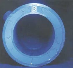
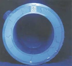
A sample photo indicates a properly hydrated cement matrix.
The inability of the cement column to maintain an overbalance during transition time (the time required for the slurry to change from a fluid to a solid), combined with volume reductions resulting from fluid loss is the most widely accepted cause for gas migration. Methods of improving the success ratio of preventing gas migration have included using compressible cement slurries such as foamed cements and slurries with low filtrate-loss properties. Other slurry properties that can be altered to help reduce CVFs include reducing cement transition times and slurry rheologies.
Past remediation efforts
Gas shutoff technology is important for the industry because CVF could indicate a possible leak of high-pressure zones into shallower formations. This type of leak may cause environmental concerns relating to potable water sands or cause shallow drilling hazards on adjacent new wells. Also, some fields have limited gas-handling surface equipment preventing the production of CVF. Therefore, many wells have been and will continue to be remediated for CVF.
Traditional remedial techniques include cem-ent squeezes, gel squeezes, bridge plugs, patch-es, scab liners, and straddle packers. Cement and gel technologies are typically used for behind-casing repair, and mechanical workover options are usually confined to repairing the tubing or casing.
Cement technology is a standard remediation technique for shutting off unwanted gas or water production. Cements provide a strong, near-wellbore block of gas production and are able to fill perforation tunnels, channels behind pipe, and washout zones behind pipe. Cement that has adequate strength development and other ductility properties can be designed to withstand future fracture treatments and acid stimulations. However, cement has limitations, such as difficulty penetrating deeply into porous rock of a potential gas source or microchannels that develop from cement sheath cracking or poor mud displacement.
Like cement, polymer gels have been used for gas remediation and water shutoff. Gels can provide an in-depth block to gas production by penetrating porous media and crosslinking in-situ. When their molecular weight and polymer concentration are adjusted, gels can be tailored as flowing or hard-ringing. Gels are limited by their inability to provide strong resistance without porous media, such as in voids and cavities behind pipe. If voids are present behind pipe, gels have to be overdisplaced to be placed within the matrix. Determining void volumes is a major uncertainty in designing gel gas-shutoff treatments, and gels are also susceptible to invasion of wellbore fluids.
Given the strengths and weakness of cement and gel systems individually, an existing hypothesis combining the two technologies was modified to maximize strengths and minimize weaknesses. However, the existing hypothesis was applied to producing wells to help isolate unwanted gas production, hence improving crude oil recovery and minimizing surface gas-separation equipment.
Reoccurring CVF
Several wells were investigated to discover why CVF reoccurred after initial squeeze-cementing efforts indicated success. The investigation included the review of well files, including the squeeze-cementing procedures, analytical analysis of drilled cement and fluid samples from these wells, and duplicating field conditions of temperature and pressure with initial placement conditions.
A review of the well files indicated that some of the cement plugs were tagged with drill pipe in different locations than intended, drilled-out very soft or were washed-out of the casing, or had large fluid and gas voids located in the planned continuous plug. These findings indicated that some of the original cement slurry did not set as intended because of:
- Contamination of the neat cement before mixing
- Formation fluid influx after placement
- Cooler than expected well temperatures
- Contamination of the neat cement during mixing.
Contamination
To help determine the root cause of the cement-plug issues, the cement manufacturing and bulk handling procedures were first probed. Dry cement samples from the manufacturer, bulk plant locations, and bulk delivery systems were analyzed to discover if any foreign materials were introduced and to determine if proper levels of cement minerals were present.
The analysis indicated that the dry cement samples from the manufacturer and service company locations fell within the API specifications and were not contaminated by any foreign substance. Therefore, the cause for improper set occurred after the delivery of the dry material to location. Further, because the recorded density charts and laboratory testing showed that slurry was mixed properly and would set as planned, the investigators concluded that the contamination must take place while or after the slurry is placed in the well.
Formation fluid influx
The investigation determined that on two wells the cement top was high on top of the retainer, and on one well the balance plug was tagged high. On the first two wells, the investigators determined that the most probable cause of these occurrences were leaking or malfunctioning cement retainers. In these cases, the retainers were set on wireline and most likely contributed to the contamination of the cement slurry via formation fluid influx.
On the well where the cement plug was tagged high, the maximum squeeze pressure did not exceed formation pressure. The inability to achieve sufficient squeeze pressures may have allowed formation fluids or gases to penetrate the unset cement slurry.
In all cases the slurries were placed without obtaining maximum squeeze pressures, and the placement was terminated due to the safe working time of the slurries.
Cooler well temperatures
Laboratory analysis of cement slurries has traditionally been performed between 15° and 20° C. Although this is usually adequate for pumping times (these temperatures are the maximum the slurry will encounter during placement), these temperatures are not necessarily indicative of wellbore temperatures at depths shallower than 400 m.
Thaumasite
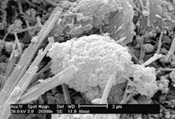
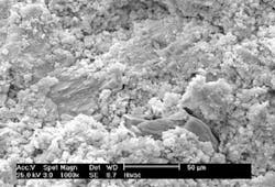
Development of thaumasite usually occurs during the hydration process when the temperature is low (<20° C) and sulfate and carbon dioxide are present. Analysis of the drilled cement samples showed the development of thaumasite. Thaumasite is a hydration mineral that is similar in chemical composition to ettringite, though thaumasite does not allow the cement crystals to grow together. Thaumasite is caused by the presence of sulfate and carbon dioxide in the slurry or setting cement.
These two compounds form thaumasite by redirecting the normal hydration process. Thaumasite causes the cement to develop small, discrete particles as opposed to a hard, unified mass.
The presence of thaumasite was good evidence that the slurries had been invaded with sulfate and carbon dioxide prior to the slurry setting. This finding lead to further investigation of actual wellbore temperatures, which indicated temperatures as low as 5° C. The presence of thaumasite also would help explain why some of the cement plugs drilled very soft or were washed out of the well. Basically, the cement hydrated and set. However, the thaumasite truncated the cement crystals from bonding together to form a solid mass.
Preventing thaumasite
When looking for external sources of sulfate and carbon dioxide that could invade the cement slurry, two probable sources present themselves: the mix water and the formation fluids.
Testing cement mix-water chemistry and temperature onsite is always recommended for quality assurance. The following ranges are recommended for cement-job mix water.
- Chloride < 3,000 ppm
- Sulfate < 1,500 ppm
- Carbonate < 90 ppm
- Bicarbonate < 1,000 ppm.
The most effective solution to sulfate attack has been the use of pozzalan additives in the slurry, and the use of short transition-time slurries. The pozzalan material also lowers the permeability of the set cement, which helps to prevent the invasion of formation fluids into the set cement sheath or plug. Pozzalan slurries also reduce transition times.
A short transition-time slurry set helps prevent the influx of formation fluids by reducing the time that measurable hydrostatic pressure is not subjected to the formation. Shortening the transition time is especially difficult when the surrounding well environment is below 15° C. Therefore, a successful slurry should be placed and set quickly in a cool environment so that the formation fluids cannot influx the setting slurry.
Building a seal
If a long-term seal was formed by the initial abandonment of a well, CVF would not reoccur. Although many of the past squeeze procedures seem to accomplish the initial goal of containing CVF, over time the flow re-establishes itself, and the abandoned well must be re-entered and abandoned again. Because whole cement cannot enter the formation's permeability, squeeze cementing alone may not provide a gas-tight seal of source zones.
One documented successful procedure is the use of polymer gel ahead of the squeeze cement. This procedure helps push the formation fluids away from the wellbore. It also helps decrease the formation permeability to greatly reduce possibility of return flow of the formation fluids to the setting cement or wellbore. Polymer gels can enter microfractures in a failed cement sheath or dehydrated mud cake, further improving the seal of a gas source zone. Cement expansion additives help prevent gas migration and increase bonding to pipe and formations.
Improved solutions
Based on laboratory results and post-job reviews of failed remedial attempts, the following guidelines are recommended for preventing CVF:
- Use a chemical wash ahead of the treatment to help remove the presence of sulfate and carbon dioxide in and near the wellbore
- Use a permeability-sealing fluid ahead of the squeeze cement with an expansion additive slurry. This fluid will enter the formation and form a gel that blocks the formation's permeability and near-wellbore microfractures
- Use the formulated squeeze slurry, which has a short transition time and thaumasite-prevention
- Use mechanical set-cement retainers to help provide better isolation. Typically, mechanical set retainers seal better because a higher setting force can be applied on the sealing element. Also, mechanical tools set slower than wireline tools, which allows the packer element to compress further than with a wireline setting device. This should result in a better isolation seal in old or corroded casing
- Attempt to obtain a squeeze pressure greater than the pressure in adjacent source zones. Unless other factors present themselves, the general guideline is to apply at least 5 to 7 MPa (megapascal - 145.038 psi) on shallow formations and 10 to 15 MPa on deeper source zones. This application helps ensure that the final squeeze pressure is above the source zone's pore pressure. By obtaining a higher pressure in the cement slurry, the chance of formation fluid influx into the setting cement can be reduced.
Case histories
In October 2001, 20 wells were plugged and abandoned with the improved solutions. Results from these squeeze operations are contrasted to a Year-2000 abandonment program on 11 wells. The Year-2000 abandonment program did not use the improved solutions outlined in the previous section. The requirement before starting a new squeeze job is to obtain a 7-MPa squeeze pressure.
The Year-2000 abandonment project of 11 wells (three zones per well) achieved the following:
- On five of the 11 wells (or 45%), two successful squeezes were executed in only one day
- On the remaining 55% of the wells, only one or less squeezes per day could be executed because of the long hesitation period to achieve to squeeze pressure
- On six of the 11 wells, the production zone was squeezed successfully on the first attempt (55% success)
- The average number of cementing days to achieve the abandonment objective was 3.3 days per well
- None of the 11 wells had CVF's pre- or post-treatment.
The 2001 Celtic field abandonment project of 20 wells (three zones per well) achieved the following:
- On 16 of the 20 wells (or 80%), two squeezes were executed in only one day
- On the remaining 20% of the wells, only one or less squeezes per day could be executed
- On 14 of the 20 wells, the production zone was squeezed successfully on the first attempt (70% success)
- The average number of cementing days to achieve the abandonment objective was 2.5 days per well
- Of these 20 wells, eleven had CVF's. After incorporating the improved solutions presented, seven of the wells had immediate shutoff of the CVF. Buildup analysis on the remaining four wells indicated flow dissipation.
For the 2001 project, 1.08 attempts per zone were required to achieve a successful squeeze. The typical industry rate for the field is 1.4 attempts per zone.
Based on rig cost savings, shorter job time, and a reduced number of total jobs, a net economic value of $71,000 was created during the 2001 project.
Conclusions
Based on the information, the following conclusions can be made:
- Wellbore conditions exist that allow the development of the thaumasite mineral in cement
- Thaumasite prevents a hard set of a cement plug
- Improved remedial cementing solutions were developed to help prevent the development of thaumasite and to help obtain a gas-tight barrier of source zones
- Results from executing these improved solutions show that CVF can be successfully mitigated
- The improved solutions can be executed in a shorter period of time than previous oper- ations.
Acknowledgments
The authors thank the management of ExxonMobil and Halliburton for their support and permission to publish this paper.
Editor's Note: This is a summary of SPE 76333


