PART II: This is Part II of a two-part series on new polyester rope and anchor results from tests. Part I appeared in the February 2000 issue.
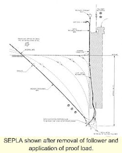
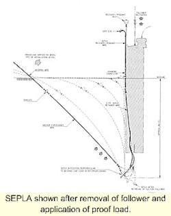
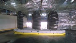
SEPLA shown after removal of follower and application of proof load.
Without accurate information on penetration depth, it is difficult to establish an anchor's ultimate capacity. Higher safety factors may be required to cope with acceptable depth positioning tolerances and additional mooring line length may be needed to deal with geographic positioning tolerances. In areas with a number of seafloor obstructions inside the mooring pattern, imprecise anchor placement may present severe problems.
Earlier, Aker Marine Contractors (AMC) conceived the suction embedded plate anchor (SEPLA) and embarked on a program to develop this new anchor type. The SEPLA combines the technical and economic benefits of suction embedded anchor (SEA) and vertically loaded anchor (VLA), without some disadvantages discussed earlier (Part I).
Plate anchors have been used for fleet moorings by the US Navy for a number of years and are now considered to be a mature technology. The Naval Civil Engineering Laboratory (NCEL), over a period of years in the late 1980s and early 1990s, tested and developed several methods for installing plate anchors, including pile driving, vibratory hammer, and explosive embedment techniques. As reported by the Naval Facilities Engineering Command, at least 250 plate anchors have been installed to date using these installation techniques. No plate anchors were installed using suction embedment.
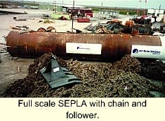
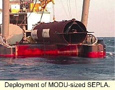
The SEPLA is a plate anchor that uses a suction follower for embedment to design penetration. For installation, the SEPLA is mounted in slots at the bottom of the follower and retained by the mooring line and recovery bridle. One suction follower can accommodate a range of SEPLA sizes with minimal modification. Depending on the size and weight of the SEPLA and suction follower, the follower/SEPLA unit can be deployed from the deck of an anchor handling towing vessel (AHTS). The mooring line is connected to the SEPLA and the top of the suction follower during deployment and is spooled off a winch installed on either the SEPLA installation vessel or a separate AHTS. For very large permanent moorings, the larger follower and SEPLA may require deployment from a heavy lift or derrick vessel.
With the SEPLA slotted into its base, the suction follower is lowered to the seafloor, allowed to self-penetrate, and then suction embedded in a manner similar to a SEA. Once the SEPLA has reached its design depth, the mechanism that secures the SEPLA and mooring line to the follower is released by the remotely operated vehicle (ROV). The pump flow direction is then reversed and water is pumped back into the follower. The follower then moves upward, leaving the SEPLA in place. Tension in the recovery wire, in combination with the positive pressure provided by the pump, extracts the follower from the seafloor. The follower is then recovered onto the installation vessel for insertion and deployment of the next SEPLA.
Immediately after embedment, the SEPLA will be in a vertical orientation with a small submersible buoy supporting a recovery bridle. At this time, the mooring line is tensioned by the installation vessel in the direction in which the SEPLA is to be loaded. This initial tension rotates or "keys" the SEPLA, so the fluke is nearly perpendicular to the direction of the load.
Design basis
The initial SEPLA geotechnical design methodology was based on work performed by NCEL on direct embedment anchors. This work is presented in NCEL's Handbook for Marine Geotechnical Engineering. In close cooperation with the Norwegian Geotechnical Institute (NGI), AMC later developed specific design methodology for the SEPLA that covers embedment, recovery, keying, plate anchor holding capacity, and recommended factors of safety. With adequate soil data, the reliability of the SEPLA can be favorably compared with piled or shallow foundations using a partial safety factor format found in industry recommended practices. Empirical relationships, such as weight-to-holding capacity, are not applicable and were specifically avoided.
As with SEAs, the resistance to embedment consists of the cumulative skin friction along the external and internal surfaces of the follower, follower buoyancy, and pile end tip bearing. Added to this is the skin friction of the SEPLA surfaces, SEPLA buoyancy, and end tip bearing of the fluke and shank. The follower design has to consider a range of soil conditions, taking into account the extra resistance caused by the SEPLA. During the SEPLA embedment tests in the Gulf of Mexico in 1998 and 1999, the follower self-penetrated under its own weight about 40% of its length. As the soil shear strength was known from borehole tests, but not the soil sensitivity, the apparent soil sensitivity was back-calculated from the self-penetration distance. We were then able to verify this value later in the tests by comparing actual and predicted embedment and extraction pressures, in addition to pullout forces required to remove the follower without pumping. Good agreement was found between the actual and predicted values.
It is important that both SEAs and suction followers have adequate venting incorporated into the top of the pile cap. There are number of ways to accomplish this. AMC has used one or more butterfly valves for this purpose on SEAs designed to date. If the water trapped inside the SEA or follower cannot discharge quickly enough with minimal back pressure, the SEA will tend to "stand" on the column of water inside the pile and tilt excessively during self-penetration.
Over-consolidated clays
Deployment of MODU-sized SEPLA.
Soil conditions at many deepwater locations (1,000 meters plus) throughout the world, tend to be normally or over-consolidated clays. As the SEA or suction follower penetrates the clay, the structure of the clay will be disturbed. This leads to increased pore pressure and reduced strength in a zone surrounding the walls of the structures during the penetration process.
When penetration stops, consolidation will start and the clay will regain strength (also known as setup effects). Experience from pile and SEA installations has shown a relatively good correlation between remolded shear strength and measured skin faction. Thus, if soil sensitivity is known, it can be calculated as the inverse of soil sensitivity.
At potential SEPLA installation sites, a range of soil sensitivities is usually reported. Thus embedment resistance is calculated for both upper and lower bound adhesion factors. Embedment resistance versus penetration depth, expressed in terms of embedment pressure, is calculated from the mudline to the final penetration depth of the SEPLA. These values are then compared with the upper and lower bound values of allowable pressures.
As with SEA embedment, the allowable pressures are based on preventing the internal soil plug from being displaced upwards. This so-called plug heave would prevent further follower embedment and may cause damage to the installation pump. All these factors are considered in the SEPLA design.
The SEPLA's functional requirement is to resist the specified maximum factored mooring line load without undergoing significant displacement both in the direction of the applied load or vertically (gradual pullout). Anchor rotation to adapt to changes in load direction is not considered critical unless repeated rotations result in a gradual loss in penetration depth. The SEPLA holding capacity is primarily related to its plate area and the undrained soil shear strength at the penetration depth. Normally, soil shear strength and SEPLA penetration into the soil are directly related (deeper penetration results in higher holding capacity).
SEPLA holding capacity can be divided into short and long-term capacities. The short-term capacity is defined as the capacity under load application where the soil behavior is predominantly undrained. For soils with low permeability like plastic clays, this would be the typical situation during storm conditions.
Long-term capacity is not considered critical for deeply embedded plate anchors in normally consolidated plastic clays. For SEPLAs subjected to long term quasi-static loads, like mooring line pretension loads in permanent installations, the effective stress conditions around a plate anchor will gradually change as the excess pore pressure dissipates. In practice, this means the soil strength is now a function of the effective drained soil strength parameters. These soil parameters will give a theoretical long term capacity value higher than the short term for normally consolidated soils.
With respect to cyclic loading, it has been NGI's experience with analyses of SEAs in highly plastic Gulf of Mexico clays that the cyclic shear strength under this type of loading exceeds the static undrained shear strength. Thus, the negative degradation effects are less than the positive strain rate effects on the undrained shear strength.
Testing and performance
In April 1998, AMC performed small-scale model tests of the SEPLA in a clear synthetic clay known as Laponite. The test objectives were:
- To determine that the follower could be repeatedly separated from the SEPLA without disturbing SEPLA orientation and depth
- To establish that the SEPLA could be keyed (rotated) to both 45° and to a full 90° with only nominal loss of penetration
- To optimize anchor design, and to minimize loss of penetration during anchor keying
- To determine suitability of rigging arrangement
- To determine the relationship between ultimate pullout load, keying loads, and SEPLA recovery loads.
The model tests provided valuable data for subsequent development of the SEPLA concept and gave AMC the confidence to design and fabricate a prototype follower and test the SEPLA. The initial test SEPLA was relatively small and designed to have an ultimate load capacity of about 350 kips.
The follower, sized to allow installation of SEPLAs with ultimate pullout capacities of up to about 1,750 kips, has dimensions of 14 ft in diameter by 85 ft in length and weighs about 100 tons. This follower is capable of installing SEPLAs for taut leg moorings for large mobile drilling units and smaller permanent floating production facilities.
The initial field test program, conducted in about 150 meters water depth in the Gulf of Mexico confirmed the initial design work, installation techniques, anchor capacity, and recoverability of the suction follower and SEPLA. The SEPLA was instrumented to provide a time history of anchor tilt and translation through the soil.
AMC constructed a 1500-kip capacity SEPLA suitable for application for drilling unit moorings. This SEPLA was tested as part of a JIP, sponsored by BP, BHP, Chevron, Mobil, and Vastar. After successful installation of the SEPLA (and a section of Marlow Rope's torque-matched polyester mooring line), the plan was to attach this mooring to mobile drilling unit Ocean America. Due to winch failures on the installation vessel and the bridle release mechanism on the follower, the program was delayed. In October 1999, AMC successfully installed a Polyester/SEPLA test mooring this time using the new AHV and construction vessel Cal Dive Aker Dove. After completion of deployment, which went flawlessly, the mooring was subjected to a tension of almost 400 tons using both the Cal Dive Aker Dove and Seacor's Marine's new AHV Seacor Vanguard pulling in tandem.
Anchor movement was imperceptible from the vessel (but instrumentation, once recovered, will record this movement). Installation of the fully instrumented SEPLA took about 1.5 hours after the follower reached the seafloor. The mooring was then attached to the Ocean Victory in about 1,500 meters water depth. Recovery was undertaken in November 1999, at which time the polyester rope was inspected, analyzed, and break-tested and the SEPLA motion data downloaded for analysis. The test program was approved by the American Bureau of Shipping and US Minerals Management Services (MMS), and witnessed by ABS and the JIP clients.
In November 1999, the Norwegian Geo technical Institute (NGI) was engaged by Saga to perform pull tests (land) of various different plate anchor types, including the SEPLA. AMC fabricated and delivered a SEPLA according to the requirements of NGI. The results are proprietary and have not been published, but the SEPLA apparently did exceed design performance. This year, AMC plans to perform further documented and instrumented tests of a SEPLA in a Norwegian fjord where the soil conditions are accurately known. These tests are expected to confirm results already obtained and complete the development of the SEPLA as a product. Through the work AMC has accomplished, the deployment techniques and installation procedures of polyester moorings and the SEPLA have reached an advanced state of development.
Current, future developments
AMC is currently developing a new subsea mooring connector that will allow either steel or polyester mooring components to be attached to SEPLA forerunners. This connector has now reached a stage of design and development where testing is expected to be completed by the end of the first quarter of 2000. AMC plans to offer a service that will allow a complete set of SEPLA anchors to be installed and initially pull-tested on one vessel trip. Once this has been achieved, then one or more vessels can attach specified mooring components to the SEPLA forerunners, drastically reducing deployment times and costs. This will also allow SEPLA anchors to be pre-installed around a subsea production template to provide anchoring for rigs engaged in completion and intervention activities associated with the subsea wells. This will eliminate the requirement for DP vessels in ultra-deepwater and will provide anchoring in areas where the seafloor is cluttered with subsea structures and pipelines.
Conclusions
Recent work performed by AMC (some sponsored by industry), advanced the state-of-the-art for deepwater mooring and anchoring and permits deepwater operators to use polyester TLM technology in all deepwater areas of the world. Considerable experience was gained in the handling and deployment of polyester allowing an understanding of equipment requirements and special considerations to ensure long-term service and reuse of the ropes.
Special consideration needs to be given to the design of polyester TLMs and installation techniques to ensure that polyester does not come into contact with the seafloor. When six-strand wire is specified in a polyester TLM, only torque-matched polyester rope construction should be used.
Mobile drilling units are expected be moored with polyester (either CM or TLM) within the next 12 months. Rig mooring experience with polyester and/or SEPLA mooring components should give operators confidence in using this technology for permanent moorings. Further AMC developments (subsea connector) are also expected to enhance installation techniques and further reduce deployment and operating costs. This will allow moored vessels to compete with DP in ultra-deepwater even more effectively.
References
Please contact the authors for a references listing (Aker Marine Contractors - Houston).
