This is the standard procedure followed in an SCR analysis/design.
Deepwater offshore development requires efficient, reliable, and cost effective riser solutions. Today, the industry is addressing designs in the 5,000-ft water depth range and potential developments in up to 10,000-ft water depth are under consideration. While many riser solutions may be considered for such developments, the steel catenary riser (SCR) concept has gained a great deal of favor due to simplicity and cost effectiveness. In essence, the riser becomes an extension of the flowline or pipeline to which it is connected. The use of metallic pipe avoids many of the complications involved with the use of flexible pipe or composite materials.
Despite these advantages, the design of a deepwater SCR system is a complex process with considerable uncertainty. Problems arise from different sources across several disciplines, thus a multi-disciplined approach is necessary. Potential problem areas include a large number of project interfaces, complex hydrodynamic responses, SCR interaction with the seabed, sensitivity to host vessel motions, installation methods, flow assurance, and project schedule requirements. Add to this the evolving and often iterative nature of many deepwater development scenarios and the key role performed by the risers, and the challenge of effectively managing the riser design becomes apparent.
Design process
From a technical and project perspective, the key issues associated with deepwater riser design may be summarized as: layout and configuration, flow assurance, materials and sizing, riser global analysis and mechanical design, procurement-fabrication-installation, technology development-qualification testing, QA/verification, OIMR strategy, interface engineering, project schedule, and health, safety, and environment issues. - The figure shows a compilation of results for a number of different platforms, SCRs, and sea-state conditions.
To aid the successful management of these issues, some important guidance points need careful consideration during project execution. As a project phase is completed, each of the design issues cited need to be addressed to an appropriate level. This will enable confident continuation to the next phase. Design issues should be considered in parallel, when practical. This will have significant implications for project resources and organization.
Some of the "riser" issues also may have an impact on the project as a whole. For example, fatigue design is often a dimensioning issue for deepwater SCR, and may influence selection of vessel type, hang-off location, hang-off detail, and minimum riser spacing. Thus at the concept stage, the design iteration may involve the development scenario as a whole rather than just the riser system.
Interface issues
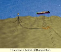
This shows a typical SCR application.
Interface issues should be worked in terms of scope of work matrix defining responsibilities, plus an interface plan detailing data requirements and associated need dates. All date conflicts should be resolved as soon as possible in order to avoid costly delays later in the project. In addition, battery limits should be selected with care, preferably to coincide with physical system limits.
For example, an export SCR should be considered as part of the pipeline system to which it physically belongs rather than as part of the floating facility to which it is attached. This will enable the pipeline system to be engineered, procured, installed, commissioned and operated as a single system with clear responsibilities in place during each project phase.
Verification of key SCR results, in particular, the dynamic analysis should be planned as part of the design process. All critical results should be checked, if necessary through independent analysis.
The use of components (or manufacturing plants) that are not field proven should be approached with caution. If technology development and associated qualification is necessary, identify such need and schedule work as early as possible. A good test plan with associated procedures and acceptance criteria will be critical to success.
Bearing the above points in mind, initial design will largely concern route selection, layout, flow assurance, pipe sizing, and riser global analysis. This later activity includes consideration of static, extreme, interference, accidental, and installation loads within the overall design iteration process. However, in many cases the main dimensioning condition is the fatigue performance of the riser. This aspect of SCR design will be considered in more detail in the remainder of this article.
Fatigue assessment
The main fatigue drivers for a deepwater SCR riser design include vessel motions, direct wave loading, and vortex-induced vibrations (VIV). These effects may be categorized as follows:
- Vessel motions: Long-term variation in mean offset; second order slow drift motions; first order motions (RAOs); vessel VIV (in case of SPAR), set-down (in case of TLP), and vessel motion induced riser VIV
- Direct environmental loads: waves and current (SCR VIV)
- Functional loads: slugging.
Currently, it is not generally possible to consider all of these effects in a single analysis. Instead, the first and second order vessel motions are typically combined in a series of time domain simulations with other effects, then considered on a case-by-case basis. Calculated fatigue damage at selected points along the SCR is then combined by simple addition.
Typically, the riser dynamic response is calculated using prescribed vessel motions, which suggests no vessel/riser coupling in the simulation. This approach considerably simplifies the analysis method, enabling better focus on the riser system design. If such coupling effects are considered significant, they can be incorporated by using vessel motions, which account for riser system effects (obtained for example using a simplified riser system model in the vessel response calculations).
Scatter diagram blocking
The starting point for the combined first and second order vessel motions fatigue assessment is the specified long-term sea state scatter diagram for the intended site. This diagram specifies the percentage of time for which different significant wave height (Hs) and peak period (Tp) combinations apply. This information, together with the vessel motion characteristics, defines the long-term motion statistics at the SCR attachment point.
To reduce computational effort, the wave scatter diagram is usually condensed into a reasonable number of fatigue blocks or bins, for which random wave time domain simulations will be performed. The number of blocks should reflect the phase of engineering and maintain sufficient accuracy in predicted results. The robustness of the selected scatter diagram blocking scheme needs to be verified by performing a sensitivity study to quantify the effects of increasing the number of bins on fatigue prediction.
When determining the scatter diagram blocking scheme for fatigue analysis, due considerations should be given not only to the characteristics of the scatter diagram itself, but also to the vessel responses. The latter may simply involve inspecting the vessel's wave frequency (the first order) and second order response characteristics in terms of RAOs and QTFs, respectively.
The purpose is to retain sufficient definition in the wave period when blocking the scatter diagram and when selecting the representative fatigue sea-states so that any resonant (or significant) responses of the vessel, and hence riser fatigue damage, is adequately accounted for. The practice of condensing the scatter diagram without considering the type of floaters to be adopted, or their motion response characteristics, should be avoided.
Once the scatter diagram is condensed, appropriate spectral shapes need to be assigned to the selected representative fatigue sea states. While this represents individual seas well, a lower peakedness parameter is considered more suitable for fatigue analysis, due to the fact that each selected fatigue sea state represents the long-term average of all sea states within the associated scatter diagram block. This difference in spectral shape may result in significant variation in predicted fatigue damage for floaters with resonant type response such as floating production, storage, and offloading (FPSO) vessels.
Touchdown point mobility
For SCRs, short-term fatigue damage is typically concentrated in a short section of the SCR close to the mean (static) touchdown point (TDP) position. However due to long-term changes in TDP position, the fatigue damage will spread out over a longer length of pipe during the SCR's service life. The sources of TDP mobility can be natural events or planned operating practice where deemed necessary.
Natural events giving rise to TDP mobility include regular vessel draft changes, change in mean environmental loading on the vessel, and vessel slow drift motions. The effects of the latter two sources of TDP mobility are normally accounted for directly in SCR fatigue analysis. However, TDP shift due to vessel draft change is not typically included since this would introduce an additional parameter for vessel draft into the fatigue load matrix.
For FPSO or floating storage vessels, the vessel operating draft typically varies on a regular basis - 3-5 meters about its mean. This results in a shift of 6-10 meters in the mean TDP of a SCR, depending on departure angle and water depth. Assuming that vessel motions are not significantly affected by such draft changes, SCR fatigue damage (based on a single vessel draft condition) can be smoothed out over the range of the TDP movement, taking into account the long-term probability distribution of vessel draft.
This can result in significantly improved fatigue lives without the need for a multiple increase in the number of required simulations. This approach can be calibrated by undertaking a full set of simulations, including draft variation, for selected cases.
Structural damping
The Rayleigh damping model is frequently adopted in FEA computer programs such as FLEXCOM-3D. It is to be noted that such a damping model leads to frequency dependent damping ratio measured as the percentage of critical damping. In other words, different modes would have different modal damping ratios.
Structural damping is an input parameter, which has significant effect on fatigue predictions for wave frequency motions. For instance, it has been shown that for the case of a SCR attached to a semisubmersible, using a damping coefficient of 0.01, doubles predicted fatigue life, compared to the zero damping case. Since the fatigue prediction is very sensitive to the structural damping level used, care must be taken when assigning structural damping values in the global riser dynamic analyses.
For unstraked SCRs, the structural damping can be considered primarily due to energy losses in steel and coating materials, which can be shown to be very low. For straked sections of the SCR, energy loss due to friction between strakes and the pipe may introduce additional damping. However, the overall structural damping is still expected to be low. Due to the uncertainties discussed above, it is considered reasonable to assume zero structural damping in global riser dynamic analysis.
Fatigue calculation
The output from the time domain dynamic analysis will be a series of short-term (on the order of 3 hours) stress time histories at different points along the riser for each of the selected fatigue sea states. To account for differences in phase between axial and bending effects, longitudinal stresses are typically requested at eight stress points around the pipe circumference.
Rainflow cycle counting can then be performed on each stress time history to determine stress cycles for use in an S-N fatigue calculation for damage rates. The selection of S-N curve and associated stress concentration factor (SCF) is dependent on pipe tolerances and weld procedure as determined from available test data or design standards. By combining the calculated damage rates for each fatigue sea state with associated occurrence data, total fatigue damage is obtained.
The rainflow cycle counting output can also be used as input to fracture mechanics assessments using internationally recognized standards such as BS 7910. This enables allowable initial weld defect sizes to be determined as input to required offshore welding and inspection procedures.
Since the calculations cited previously involve a considerable amount of numerical processing, the procedure can be quite slow, even on modern PCs and workstations. A compilation of results is presented in terms of the root mean square (rms) longitudinal stress in the SCR at the TDP versus rms heave motion at the top attachment point. To a reasonable first approximation, the relationship is linear. Using such databases enables quick initial estimates to be made using simple spreadsheet type calculations. Such calculations can act as a useful supplement to the full time domain procedure especially during early stages of the design or when "what if" questions are asked.
An alternative approach to speed up the procedure is to undertake the dynamic analysis in the frequency domain. This requires linearization of hydrodynamic drag force and SCR structural response, particularly the seabed bound- ary condition. In addition, it is not possible to determine the short-term probability distribution of stress cycles from a frequency domain analysis with the result that additional assumptions are required.
Such assumptions can have a very significant effect on calculated lives. Although such methods can offer a significant increase in speed, full calibration against time domain results is required. The main advantage appears to be supplementing the time domain approach (during design sensitivity studies).
VIV fatigue
Considering the other sources of fatigue damage noted previously, the most significant effects are associated with VIV motions, either arising on the platform (in the case of SPAR) or directly on the SCR catenary. This is an area of ongoing research and development from which analysis improvements are expected in the future.
With respect to direct SCR VIV motions, the problem can be contained (designed out) by use of strakes. The engineering problem is hence to improve analysis methods to the point where the requirement for, and extent of, strakes on the SCR can be fully optimized. Concurrent with this work, there is a need for improved realistic current data (in terms of depth profile, direction, and occurrence) for many offshore locations.


