When shooting a 3D marine seismic survey it is important to accurately determine the positions of the sensors and of the source to enable correct binning of the data. Real time positioning systems are needed by vessels' navigators to monitor the coverage of the survey area in terms of the fold, to ensure that full subsurface coverage is obtained. This requires a pre-defined number of common midpoints, often in excess of 100, to occur in each bin.
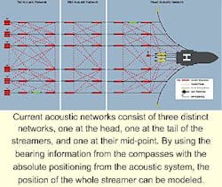
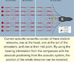
Current acoustic networks consist of three distinct networks, one at the head, one at the tail of the streamers, and one at their mid-point. By using the bearing information from the compasses with the absolute positioning from the acoustic system, the position of the whole streamer can be modeled.
While it is comparatively simple to position points on the sea's surface, such as the gun string floats, navigation buoys, and tail buoys with differential global positioning system (DGPS) or lasers, the options for the positioning of the in-sea equipment are limited to acoustic systems and compasses.
The acoustic positioning systems comprise a number of transceivers that are mounted on the streamers using conventional collars. These transceivers communicate with each other to build up an acoustic "net" of ranges.
The geometry of the network is such that the relative positions of the transceivers can be determined acoustically with considerable accuracy. By relating the network to a number of acoustic transceivers mounted on objects such as tailbuoys that are being monitored with DGPS, the absolute position of the network can be determined.
Special transceivers have been developed for mounting on different objects such as gun floats and are specifically designed to withstand the high forces produced by them. An acoustic transceiver can also be deployed from the hull of the vessel to tie the network in with it.
Three nets
Streamers currently are positioned using three acoustic networks, one at the head, one at the tail of the streamers, and one at their midpoint. The absolute positions of the head network are obtained by tying the acoustic ranges back to the DGPS-determined positions of the gunstring, ship, and often a navigation buoy.
Similarly, the tail network is tied to the positions of the tailbuoys. The shape of the streamers between the networks is determined using compasses attached to the streamer. By using the bearing information from the compasses with the absolute positioning from the acoustic system, the position of the whole streamer can be modeled.
The streamer-mounted transceivers are all battery powered and communicate with the signal processing and control unit on the ship via an inductive communication technique. This uses coils mounted within the streamers to transmit and receive signals from similar coils mounted in the acoustic transceiver, similar to the two coils of a transformer.
Data and timing information can, in this way, be passed to the in-sea equipment without the need for connectors, which would compromise the integrity of the streamers and increase cost. The acoustic transceivers mounted on the gun string and through the hull of the vessel are powered from the system controller and communicate directly with it.
New challenges
The recent launch of a number of seismic vessels with very large tow capabilities of 12-20 streamers, have created new challenges for their streamer positioning:
- System capacity: The need to position more acoustic nodes within a shotpoint.
- Harsher acoustic environments: The energy that the vessels need to tow the larger spreads can increase the levels of noise and aeration in the water column. While many of the latest generation vessels are designed to be quiet, the extra turbulence can still affect the performance of acoustic positioning systems.
- Deployment: As the seismic spreads are deployed for longer periods, the battery life of the acoustic units needs to be longer.
- Compass-free streamers: Recently seismic acquisition companies have been evaluating the use of acoustic positioning for the entire length of the streamers rather than just the three acoustic networks. When using this technique, information from the compasses is not required and overcomes many of the problems associated with them. These include calibration errors due to local magnetic anomalies and the problems of declination. Magnetic compasses are also susceptible to noise associated with the physical movement of the compass modules.
- Accurate determination of sound velocity in water: The large areas covered by the new generation of streamer spreads can include variations in water salinity, particularly when working near river estuaries. Because this can cause variations in sound velocity, it can have a corresponding effect upon positioning accuracy within the spread.
New systems
The first generation of acoustic positioning systems used a tone burst technique, which transmits bursts of a single acoustic frequency. The SIPS 1 (seismic integrated positioning system) from Sonardyne International proved to be successful. It uses three tones of different frequency per acoustic transmission. These produce redundancy in the signal and create a very reliable acoustic structure. The system is currently used on the majority of the world's seismic fleet.
The limitations of this system are the restricted bandwidth available. With a bandwidth of 50-100Hz, the system was limited to four unique frequency groups per acoustic event and confined the system to positioning a maximum of 10 streamers.
To overcome these difficulties and to meet the need of the larger streamer spreads, a new generation of acoustic positioning systems (SIPS 2) has been developed that greatly increases the number of ranges that can be collected. A technique known as code division multiplexing (CDM) is used to distinguish the different signals. It enables a greater number of acoustic ranges to be collected in a given time. This extra capacity will permit the full acoustic positioning of a 20-streamer spread.
The digital modulation of the fixed frequency carriers produces a spread spectrum signal, which provides associated advantages. These include being able to operate in noisier environments than conventional tone burst systems, which would be unable to detect the signal because of the noise. It also increases the battery life of the acoustic units by reducing the amount of transmission power needed to ensure signal detection.
Inductive communication
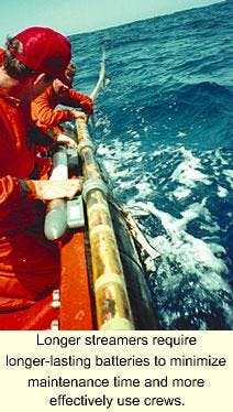
Longer streamers require longer-lasting batteries to minimize maintenance time and more effectively use crews.
The new systems also have enhanced communication with the acoustic transponders attached to the streamers. An inductive communication technique, via coils mounted in the streamers, is used and has the advantage of a high level of tolerance with the mounting of the transceiver on the streamer.
Traditionally, one of the problems with this communication method has been "cross-talk" whereby the communications of one streamer interfere with those of another. To overcome this problem, transceivers must have the ability to adjust their communication power output and normalize the signal strength at the on-board controller rack.
This ensures that the strong signal from transceivers at the head of the spread does not wipe out the weaker signals from those at the tail. It also has the advantage of ensuring that only the minimum power is used to ensure reliable communications, thereby extending the battery life.
Velocity-of-sound
All acoustic positioning systems determine the range between transceivers by measuring the time it takes for the acoustic signal to travel between them. The accuracy of any such system is therefore determined by the velocity-of-sound in water. As the size of seismic-spreads increase and the positioning tolerances become more important, on-line sound velocities are needed. Units similar to the acoustic transceivers have been developed that measure the speed of sound in water.
These units are deployed and communicate in the same way as the transceivers, passing the sound velocity information to the controller as part of the acoustic range data. This information is consequently available to the vessel navigators in real time and at a known point within the array. In areas where water salinity can change significantly along the length or width of the array, a number of these sensors can be deployed throughout it.
While the increased size of streamer spreads has introduced a variety of new technical demands, acoustic positioning technology has responded to the challenge. The result is the introduction of new systems that surpass the capabilities of their predecessors and set new benchmarks for the levels of performance that seismic surveyors can expect to work with.
