System maximizes total asset value
Sandeep Patni and Janardhan Davalath; FMC Kongsberg Subsea
A major challenge in developing a deepwater project is recovering reserves at a reasonable capex investment for flowline and riser installation. A high-integrity pressure protection system (HIPPS) is a step toward improving recoverability. HIPPS provides a pressure break between subsea systems that are rated to full shut-in pressure and the flowline and riser, rated to a lower pressure.
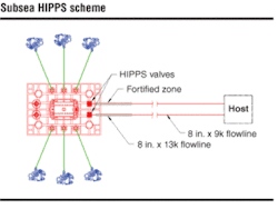
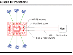
The base case for developing a high-pressure reservoir tie-in to an existing facility is to have a topsides HIPPS option. Analysis was performed using a dynamic multiphase flow-modeling tool to perform transient pressure build-up in the flowline. Flow assurance analysis provided the critical input in establishing the length of a fortified section required in the flowline. The length of the fortified section is calculated based on how far the pressure wave travels before the HIPPS valves have enough time to sense and isolate the lower rated flowline from over pressure.
The flow analysis study was divided into three objectives:
- Sizing the flowlines and risers for topsides HIPPS and subsea HIPPS options
- Defining thermal insulation requirements and studying the impact of subsea HIPPS on thermal performance
- Establishing the length of the fortified zone required for subsea HIPPS, based on dynamic pressure response.
HIPPS is a high-integrity pressure protection system.
The study assumed a typical high-pressure field in 4,000 ft of water with multiple wells to be developed as a subsea tieback to an exiting host facility 10 mi away. This field’s well shut-in pressure was 11,500 psi. The high initial shut-in pressure at the wellhead required very thick flowlines. Alternatively, subsea HIPPS could be installed, and the flowline could be de-rated downstream of the HIPPS. The most common flowline sizes of 6-in. and 8-in. underwent a comparative analysis.
This development considered multiple wells daisy chaining and producing back to the existing host facility via dual flowlines.
Subsea field architecture
HIPPS modules can be installed subsea on christmas trees, PLETs, or manifolds. Location depends on subsea architecture - single-well tieback, manifold tieback, or daisy-chain tieback. Determining the flowline/riser sizes required for the subsea and for topside HIPPS options is the primary focus.
For the topside HIPPS option, the flowlines and risers must be rated to the full shut-in pressure of the wells. A subsea HIPPS allows a majority of the flowline downstream of the HIPPS valves to be rated to a pressure less than the shut-in pressure of the wells. The flowlines can have a de-rated design pressure downstream of the fortified zone. The design pressure of the de-rated flowline is between the flowing pressure and the wellhead shut-in pressure and is based on dynamic flow analysis.
The decrease in design pressure results in considerable savings in terms of wall thickness. Thinner flowlines and risers can have a significant cost benefit in terms of fabrication and installation.
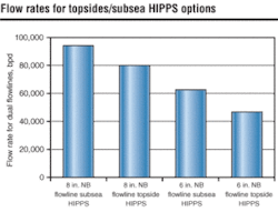
For subsea HIPPS, the length of the fortified section established from flow assurance analysis is 1 mi. Based on the length of fortified section and the thickness of the flowlines, the maximum flow rate from 6-in. and 8-in. flowlines is significantly higher than for the topsides HIPPS.
Production rates through the flowlines with subsea HIPPS are higher than with the topside HIPPS option. This is because flowline/riser thickness using a subsea HIPPS is considerably reduced, increasing the cross-sectional flow area. Topsides HIPPS constrains the production system. Several issues further exacerbate the problems:
- With increase in water cut, the capacity of the flowlines transporting produced liquids back to the host decreases
- With no pressure maintenance of the reservoir, the flow rate declines rapidly.
HIPPS features lighter, thinner-wall pipeline that translates to lower material costs and a reduction in welding and fabrication costs. It is easier to handle and transport and allows a choice of installation vessels.
Using subsea HIPPS de-bottlenecks the system and increases throughput through these lines because the pressure in the flowline and riser system drops. Compared to the topside HIPPS option, a subsea HIPPS can increase total production for a typical field 80,000-94,000 b/d, a 15% increase.
Impact on thermal performance
One of the most significant flow assurance issues with deepwater subsea tiebacks is the length of cooldown time required (the length of the time between shutdown and when the fluids fall into the hydrate formation region).
Flowline and riser fluid temperatures were reviewed based on various types of thermal strategies. A comparison of the arrival conditions against the hydrate dissociation temperature and wax appearance temperature ensured that the flowlines could operate during steady state flow without solids deposition in the lines.
The impact of using subsea HIPPS on the thermal performance has been evaluated based on pipe-in-pipe flowlines as the base case configuration. The base case insulation for the riser is assumed to be 4 in. of external insulation.
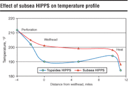
The increased flow rate relates to higher wellhead temperatures for subsea HIPPS. This may provide considerable operational advantage in terms of cooldown time. The arrival temperature using a subsea HIPPS is higher than that of a topside HIPPS because of the higher flow rates.
Using the subsea HIPPS option provides a substantial increase in flowing wellhead temperature, which creates the following benefits:
- The subsea system has a complex geometry, which causes gas liquid separation. Gas cools much faster than liquid, and a higher starting temperature at the wellhead results in a longer system cooldown time
- Subsea systems (trees, jumpers, and PLETs) cannot be insulated as effectively as flowlines. Since pipe-in-pipe is the recommended flowline insulation, flowlines have sufficient cooldown time. Higher wellhead temperature can result in a decrease in insulation requirements for the 15 K trees. In addition to insulation cost savings, the lighter weight trees are easier to install
- Part of the subsea system (tree and well jumpers) cannot be pigged. Higher wellhead temperature reduces the risk of wax deposition in trees and well jumpers
- Higher starting temperatures with subsea HIPPS result in a longer cooldown time if the insulation requirements remain
- Higher flowing wellhead temperature minimizes the risk of wax deposition downhole.
Dynamic flow analysis to establish fortified zone
The flowline must be fortified for some calculated distance downstream of the HIPPS valves. To determine the optimum fortified length, a dynamic flow analysis was performed for typical black oil and gas condensate fields to estimate how quickly the flowing pressure rises to the design pressure of the de-rated flowline.
Possible events that can cause flow to stop and result in the pressure to increase from flowing pressure to shut-in pressure include:
- Topsides shutdown caused by process problems
- Choke malfunction, unplanned opening
- Hydrate blockage in the flowline.
The worst case corresponds to a scenario in which the trapped volume (length) is the least, where pressure surges from flowing pressure to the shut-in pressure occur in a short time.
The most severe case occurs when a hydrate plug forms just downstream of the fortified section. When this occurs, the control system reaction time combined with the HIPPS valve closure time must be fast enough to avoid overpressure of the de-rated flowline.
Black oil field
A HIPPS can respond within 20 seconds and close the subsea valve to isolate the de-rated flowline from overpressure. Parametric sensitivity was performed for water cut. Two lengths of fortified sections were examined - 0.2 mi and 1 mi.
The dynamic pressure response is a function of the line pack and the pressure surge. The pressure surge for an oil and gas system is very low. The pressure rise in oil and gas system to the shut-in pressure results from the line pack.
The design pressure for an 8-in. nominal bore flowline is 9,000 psia. It takes 17 seconds to reach design pressure from trigger pressure. The criterion of minimum response time of 20 seconds is not met with a fortified length of 0.2 mi.
Using a fortified section of 1 mi gives a response time of 29 seconds for water cut of 50%. This gives sufficient time even for the secondary trigger to activate and close the HIPPS valves.
Based on 20-second response time, the length of fortified section required is 1 mi. A fortified length of 0.2 mi cannot achieve the criteria of a minimum response time of 20 seconds. The length of fortified section and thickness of downstream pipe can be optimized by performing similar studies. The length of the fortified section can be decreased further if the HIPPS control system can close faster than the 20 seconds considered for this study.
Gas condensate field
The dynamic flow analysis was repeated for a typical gas condensate field.
For the same reservoir pressure, the shut-in wellhead pressure is 13,500 psia for the gas condensate, which is higher than the shut-in pressure for the oil zone.
The pressure response depends on the fluid medium and the following two differences are observed for the two zones:
- The gas condensate zone has a higher shut-in wellhead pressure because gas condensate is less dense than oil
- Since gas condensate compresses more than oil, pressure increase is comparatively slower for the gas condensate fluid.
The pressure surge increases with an increase in water cut. However, increasing water cut results in lower flowing pressure and shut-in pressure. The reservoir pressure also declines with time; so the overall dynamic pressure response in late life does not exceed the response time requirements set for early life (higher flowing and shut-in pressure).
When flow stops up a flowline, the kinetic energy of the flow converts to potential energy, giving rise to a hydraulic surge. The highest pressure develops when flow stops. Pressure waves reflected from the other end influence the magnitude of the surge pressure.
Cost/benefits
Based on the larger inside diameter flowlines corresponding to the subsea HIPPS scenario, the field-wide production rate can be increased because of the reduced frictional pressure drop. The increase in production for 8-in. dual flowlines with subsea HIPPS is 14,000 b/d. The incremental return from using subsea HIPPS amounts to $12.6 million/month.
Studies have shown that for a short subsea tieback, the net savings in the material and fabrication of the lower-pressure rated flowline and riser tiebacks offset the incremental cost of incorporating a subsea HIPPS. This result is based on mild steel flowline/riser materials. So the net cost of incorporating subsea HIPPS in the project for the design case illustrated is zero. For zero net cost, the subsea HIPPS offers significant benefits:
- Lower offshore installation costs
- Easier offshore transportation and handling due to lighter pipes
- Higher production rates, revenue, and recoverable reserves
- Early payback with incrementally higher oil and gas flow
- Flow assurance benefits associated with higher flowing wellhead and flowline temperatures.
Installing subsea HIPPS for high-pressure deepwater fields maximizes the total asset value by accelerating the cash flow.
Editor’s Note: This is a summary of SPE 89998 presented at the September 2004 ATCE. This paper has been peer reviewed.
Terminology used for dynamic flow analysis
Trigger pressure - This pressure is usually 500 psi above the flowing pressure. This is the pressure at which the control module will start closing the subsea HIPPS valves.
Design pressure - The flowline can be de-rated to a pressure between the flowing pressure and the wellhead shut-in pressure. This pressure should be sufficiently higher than flowing pressure to allow time for the HIPPS control module to sense the high-pressure condition and close the valves.
Primary trigger - The primary trigger function activates if the subsea control module detects a pressure above trigger pressure. The response time for the primary trigger is 2 sec.
Secondary trigger - The secondary trigger function activates in the unlikely event of a primary trigger failure. The secondary trigger function activates if the topsides control module detects a pressure above trigger pressure. The response time for secondary trigger is 20 sec.
