Completion isolation valves (CIVs) were developed originally in the mid-1990s as a solution to a number of problems associated with high-angle sand-face completion operations. Specifically, they were designed to curb fluid loss in which the resultant formation damage can result in overall well productivity impairment and increased well cleanup times. In addition, there was a requirement for high integrity suspension/test barriers that could be removed with no requirement for well intervention.
However, although the first valves performed well, particularly given the immaturity at the time of the interventionless technology and especially in high pressure/high temperature applications, the debris in the well continued to adversely affect its full capabilities.
To improve its performance and reliability, many valuable lessons regarding the valve's application have been continually fed back into the design. As a result, CIV technology is improving well clean up and productivity, especially in more complex applications that are significantly different from the earlier prototype installations.
After drilling relatively deep, high angle wells, operators often suspend each well using some form of reservoir isolation device to protect the formation from fluid losses below the barrier while allowing installation and testing of the upper production completion, tubing hangers, and packers above it. Drilling and completion activity timing may be such as to require a long-term suspension of the sand-face completion prior to installation of the upper completion and christmas tree.
The traditional approach to prevent fluid loss is to install a simple flapper valve, and to suspend the well, some form of retrievable plug run on drill pipe/coiled tubing is installed. The disadvantage to these methods is that the flapper will only hold pressure from above. Additionally, a complete sand- face suspension requires a time-consuming intervention to set a plug on drill pipe or coiled tubing followed by additional runs to retrieve the plug.
Isolation valve
In conjunction with a major North Sea operator, Aberdeen-based Petroline Wellsystems (acquired by Weatherford in 1999) recognized that advantages could be accrued by incorporating a purpose-designed isolation valve within the sand-face completion. It would not only minimize operational time and expense of rigging up coiled tubing at the suspension and completion phase, but also benefit safety by reducing personnel exposure to risk.
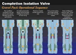
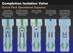
The subsequent concept envisaged a bi-directional ball valve located below a liner hanger packer assembly. The valve was run in the open position such that all required sand screen placement operations could be conducted normally. The ball valve could then be closed to form a suspension barrier, allowing the drilling rig to move to the next well location and continue drilling operations.
Feedback from the operators suggested the desirablity of extending the initial CIV/R (Ratchet) single close/open functionality to a design that could be subjected to any number of open/close cycles. The output of this was the CIV/RM (Ratchet Mechanical) variant and was manufactured in 7" and 9 5/8" sizes.
null
Months later, the rig could return and open the valve hydraulically without intervention. When used with a second valve (the HSV) to set the production packer, the CIV allowed the flow control objectives of the wells to be achieved with no coiled tubing or slickline intervention below the tubing hanger.
To ensure maximum integrity, the valve included a single seat, non-elastomeric, bi-directional ball-sealing unit capable of withstanding extremely high differential pressure ratings - up to 7,500 psi from both above and below. It was designed to ensure a minimal bearing force between ball and seat during rotation, yet guarantee that the ball and seat would not part company when direction of pressure loading was reversed. Features were included to allow sand-face service tools, such as those associated with inflating annulus casing packers, to be run through the CIV without interfering with the CIV operation. Lastly, the valve was to be activated mechanically using a shifting tool or remotely using tubing pressure cycles applied from surface.
Lessons learned
The initial CIV installations confirmed a desire within the operator community to realize the value adding benefits of interventionless tools. While the bulk of the early installations were successful, it was also apparent that there was room for improvement. Particularly in the more challenging near high pressure/high temperature (HP/HT) applications, it was clear that the overlap between the CIV operating envelope and the level of cleanliness achievable in well clean-up was not sufficient.
This resulted in debris impacting operational success. It was also apparent that a market need existed for the CIV that could not be met with the original design specification and functionality.
Four CIV/RM valves have been successfully installed and pressure cycled open on the North Sea development. In the most extreme case the CIV was closed against a 600-bbl/hour fluid loss rate.
null
For example, other operators began to look at the tool for application in their near-HP/HT (high pressure/high temperature) wells. Here, the use of the CIV allowed safe under-balance completion installation. These high-pressure wells were being completed with heavy mud/brine fluid systems necessary to control the downhole pressures. Therefore, the CIV had to be installed under conditions of extreme high debris potential and withstand severe bi-directional pressure differentials.
However, it became evident that in some cases the debris within the well had an adverse effect on the valve. Heavy barite-weighted muds were required at valve installation to balance the downhole pressures. In one application, this resulted in up to 200 ft of barite accumulating above the valve and making it difficult to operate, although the valve itself was still in good working order when retrieved.
The lessons from this work resulted in a strict application of rigorous operational hole-cleaning techniques to minimize the effect of the deposition of external debris. Nonetheless, a principal benefit of running the tool to the extreme edge of its operating envelope was that it let the designers and operators alike see what was possible. Addressing these problems was instrumental in the subsequent design of the next development.
Solution
The two major tasks faced by the designers were increasing the reliability and extending the tool's operability. The lessons of operating in high debris environments resulted in an enhanced debris management system including internal filter mechanism improvements and pressure cycle ratchet enhancements. The tools operability was addressed by the introduction of new tool functionalities and improved associated service tooling.
Feedback from the operators suggested the desirability of extending the initial CIV/R (ratchet) single close/open functionality to a design that could be subjected to any number of open/close cycles. The result was the CIV/RM (ratchet mechanical) variant and was manufactured in 7 in. and 9 5/8-in. sizes. A step change for the valve design, the RM version enhanced operational flexibility and also included significant design improvements to overcome the problems identified in the early prototype installations.
The CIV/M (mechanical) was introduced in 5 in., 7 in., and 9 5/8-in. sizes aimed at BHA (bottomhole assembly) deployment applications. A further design project resulted in the development of a 7 in. and 9 5/8-in. CIV/S (stinger) version, which recently was selected by the Ocean Petroleum Development Company of Shengli Petroleum Administration Bureau in China for the Shengli field development. In this application, the valve was operated by a stinger on the upper completion tail pipe as opposed to being activated by shifting tools.
Case history
The improved CIV/RM design has been applied in numerous wells worldwide. In recent operations for a major North Sea operator, the 9 5/8-in. CIV/RM is being run as part of a horizontal screen placement sand control completion. After setting of the screen hanger packer, the CIVs are closed with the a shifting tool (MCSO). This tool was introduced, along with the RM version of the valve, to address problems experienced with the shifting tools used with the original prototype CIV. The main advantage the MCSO has bought is a simpler and more reliable shifting tool system. The tool is less complex to assemble and operate downhole while still maintaining the essential positive indication at surface of the CIV being closed.
Once closed the screen running string is retrieved to surface. The shut CIV stems fluid losses to the formation and acts as a suspension barrier prior to upper completion installation. The upper completion is run and tested against the closed CIV. Once the surface tree is installed the CIV is pressure cycled open from surface. The end result is that the fluid loss control, suspension and upper completion test requirements of the well have been achieved with no intervention runs into the well.
To date six-CIV/RM valves have been successfully installed and pressure cycled open on the North Sea development. In the most extreme case, the CIV was closed against a 600-bbl/hour fluid loss rate.
Author
Graham Makin is the Technology Director, Flow Control, Well Servicing and DIACS for Weatherford International, Inc.
