- At the heart of the STP solution [15807 bytes] is a production connector that allows several risers from subsea wells to be connected to the ship via a submerged buoy.
One of the most attractive features of Statoil's newbuild multipurpose shuttle tanker (MST) design is that it is easily upgradeable to a production vessel (FPSO). The MST is designed to accommodate a flexible modular topside process arrangement, which can be modified between field applications where the process facility requires modification. Indeed, the modular process facility can be leased, or favorable buyback terms could be negotiated for a purpose-built unit.
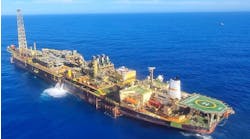
The MST combines the requirements of an efficient shuttle tanker and a monohull production vessel and is designed with the hull strength needed for permanent mooring on a field location. The vessel has a storage capacity of 640,000 bbl and is capable of performing loading from a variety of offshore installations.
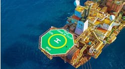
Apart from submerged turret loading operations, all other loading is performed from the vessel's stern. The vessel accommodates 55 personnel, is equipped with a navigation bridge and electrical power plant forward, three free fall lifeboats (two forward, one aft) and a forward helideck.
The turret, submerged buoy and rotating connector comprise the submerged turret production system (STP). The buoy serves both as a turret mooring system and as a connection for the subsea risers between the subsea facilities and the ship.
When not connected to the FPSO, the buoy floats submerged at an equilibrium position 25 to 45 metres below the surface, dependent on the in situ water depth. When locked to the FPSO in a conical recess in the ship hull, it transfers the forces between the mooring system and the FPSO. In this mode, rotation between the vessel and mooring system is accommodated inside the buoy structure.
Typically, the mooring system configuration comprises:
- a drag, piled or suction anchor system
- a chain segment, normally K3 studless
- an upper wire segment, with mooring line buoyancy elements incorporated in the upper portion of the line in water depths over 250 metres.
The system is designed to maintain the vessel in weather conditions as specified in the field design basis and is generally based on DnV POSMOOR requirements.
Vessel weather vaning is achieved through use of the rotating connector (swivel assembly). The assembly consists of a central cartridge, an upper housing connected to the FPSO and a lower housing that includes all riser and umbilical connections to the buoy. The connector is disconnectable and the cartridge can be extracted from the lower housing.
The STP buoy is pulled into the vessel recess by a traction winch and is then locked to the hull structure by a hydraulic locking system backed by a mechanical locking arrangement. Locking systems are located in a submerged compartment in the bow structure and are sealed from the sea, both when the buoy is attached and when the cone hatch is locked during vessel passage.
On the MST Berge Hugin, ABB has supplied the total electrical package. Vessel power is provided by diesel electric power units, with associated switchboards and auxiliaries arranged following the split system, with systems symmetrically divided by a longitudinal bulkhead in the centre line. There are two completely independent plants where each machinery space incorporates two Wartsila Diesel dual fuel (diesel gas) generator sets, each generating 5MW at 6.6kV for a total of 20MW from both engine rooms.
Main propulsion is via a synchronous 12MW AC motor, while the double-armature bow thruster and azimuth thruster motors are powered by asynchronous motors. The Berge Hugin's 4 x 1,400kW cargo pumps and 2 x 350kW ballast pumps are each speed controlled by ABB PWM frequency converters. The vessel is designed for two bow thrusters and two retractable azimuthing thrusters with one main propeller with high lift rudder aft.
Production scenarios
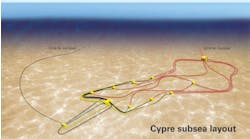
The concept was initially targeted at small, marginal fields with typically five to seven subsea wells which can either be tied back directly to the vessel or arranged on one or more manifolded templates or clusters.
With judicious subsea manifolding, which is being developed by Statoil in parallel with Hinge Over Subsea Template (HOST) technology, the system could accommodate up to 20 wells depending on flowline configurations adopted at each template. In most production scenarios, the STP buoy is likely to accommodate 8-10 main product passes through the turret and buoy.
The MST vessel is prepared, with regard to strength, stability and arrangement, for the installation of a process plant of 3,500 tons. It is also equipped with seawater cooling, steam, plant air, instrument air and deluge water for small to medium-sized process topsides.
A modularized topside process layout has been developed, giving increased flexibility in terms of process re-use and modification. The design centres around a central process manifold designed for the inclusion of or exchange of process units. These are limited to three different skid sizes, each designed with a standard support structure to mate with the reinforced support locations on the deck. A typical layout can accommodate two-stage separation, water and gas reinjection.
It is anticipated that a process module pool will be established for the purpose of leasing modules. This approach also increases the re-use value of the process equipment, provided the modules are designed to the minimum requirements established for the pool. Topsides installation is possible within three months provided that modules are available. Capacity modifications, through the additions of new or exchange skids, can be performed in one or two months.
Reference: Underwater Technology Conference, Bergen, March 1996
Copyright 1996 Offshore. All Rights Reserved.


