PRODUCTION TECHNOLOGY: Part I: Novel multiphase hydraulic submersible pump used on Captain
PART I: This is Part I of a two-part series dealing with multiphase hydraulic submersible pumps. Part II will appear in a subsequent issue.
The continuing drive to maximize recovery rates and quantities from oil assets is increasing the requirement for the development of reliable artificial lift systems that are flexible enough to operate in free gas cap areas, at greater draw-downs, and on wellstreams where the bottom-hole pressures are closer to the bubble point.
Such applications are becoming increasingly common as we attempt to tie-in previously considered problematic assets to existing infrastructure for low-cost incremental production. This includes cases where there is a desire to operate with lower bottomhole pressures to squeeze more barrels from mature wells.
One of the main technical challenges associated with this trend is the development of pumping systems that are capable of operating on varying well streams containing significant quantities of free gas, either as a homogeneous mixture or as slugging flow. Conventional downhole centrifugal pump designs are limited in the amount of free gas void fraction (GVF) that they can handle (around 40%), unless fitted with in-line separation equipment. This performance also falls off dramatically at off-design conditions, thus limiting the effective operating range.
A further drawback in the use of mechanical rotary separators at pump inlet is that they are an additional complexity that can compromise the system reliability through imposition of higher shaft loadings. However, with significant reserves capable of being produced at GVFs above this level, there remains a clear need for the development of enhanced pump designs capable of continuous, reliable pumping at elevated gas levels.
Texaco and Weir collaborated in the development of an enhanced version of Weir's hydraulic turbine-driven submersible pump (HSP), which promised the ability to pump fluids containing from 0% to over 60% free gas at pump suction. A successful phased development program consisting of laboratory screening tests of suitable designs on water/gas mixtures, and progressing to multiphase hydrocarbon testing at Texaco's R&D facility, culminated in the field trial of a new design of HSP in a well in the Captain Area A development commencing in June 1998. The Captain Field is in the UK sector of the North Sea.
Area A development
The Captain field has 19° API crude oil, with 88 centipoise (cp) viscosity at reservoir pressure of 1,300 psi and 87°F. The solution gas/oil ratio is 130 cu ft/bbl oil. These conditions dictate that artificial lift is required in order to produce the reserves in the majority of circumstances.
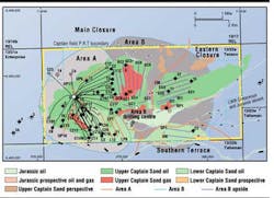
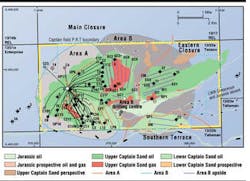
The large aerial extent of the field encompasses four distinct oil bearing sands, one of which is the Upper Captain Sand containing an extensive free gas cap in the east. The first phase of field development (Area A) targeted the largest recovery that could be achieved from one drilling center, while avoiding the gas cap area.
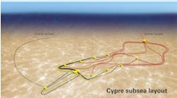
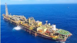
The Area A drilling center, approximately 1.5 km west of the floating, production, storage, and offloading (FPSO) vessel was completed in January 1997. The facility consists of an FPSO and a wellhead protector platform (WPP 'A'). The Captain FPSO was initially capable of processing 65,000 b/d of oil, and up to 260,000 b/d of liquids, and has a storage capacity of 560,000 bbl. A shuttle tanker offloads the accumulated crude for delivery. The produced water is cleaned of residual oil and solids and pumped at high pressure through injection wells back into the oil reservoir, where it assists oil recovery. Electric submersible pumps (ESPs) are exclusively used to provide the artificial lift from the Area A wells.
Lessons learned
The production experience from Area A, following start-up in early 1997, indicated that the occurrence of free gas coning can be much more severe than predicted. A number of wells, which appeared to be some distance away from the mapped gas-oil contact, experienced elevated producing GORs for some months.
In some wells, these conditions permitted free flow to be used. In others, this was not the case, and production was characterized by frequent gas locking of the ESPs and associated downtime.
On the basis of the early Area A production experience, coupled with new reservoir simulations, the maximum producing GOR levels predicted for the gas cap region of Area B were significantly increased. These elevated gas levels would have an obvious impact on the selection of artificial lift technology.
Turbine-driven pump
The basic design of the HSP has been around for 16 years and has been applied to water-lift as well as oil-lift duties. One of the most successful applications for the technology has been the use of an HSP to produce geothermal water for a heating plant. This application involved the seasonal operation of a pumpset in brine at up to 200°F for more than 12 years, without the need for any workover. The turbine drive concept differs from the more common ESP used for artificial lift in several ways. The unit:
- Is driven by a high pressure liquid multi-stage axial flow turbine and therefore has no need for power electrics downhole
- Operates typically at twice the speed of an ESP with a higher driver power density, requiring fewer, smaller stages, resulting in a much more compact unit of 3-4 meters length
- Lacks mechanical seals and contacting thrust and journal bearings that have been eliminated from the design of the HSP through the use of throttle bushings and hydrostatic bearings
- Has an inherent variable speed capability in response to pumped fluid mixture composition.
The current designs of HSP are engineered for erosion and abrasion resistance through careful design of fluid profiles, clearances, and the extensive use of super duplex steel, high hardness alloys, engineering ceramics, cermets, and hard coatings in critical areas.
Multiphase HSP design
For multiphase duties, where gas-handling operation across a wide range is important, the impeller within the pump end must be designed as a compromise between generating sufficient head per stage and preventing centrifugal separation of the fluids. In this way, buildup of gas at the impeller hub, which leads to gas locking and breakdown of head generation, can be suppressed until very high inlet GVF. The phased development test program produced a design of impeller capable of handling 57% GVF at 30% of best efficiency point (BEP) flow and over 90% GVF at flows greater that 75% of BEP flow.
The improved multiphase performance was achieved on live hydrocarbon testing at the test facility using Captain crude, methane, and brine. As well as demonstrating enhanced gas handling capability, the tests also proved the ability of the new design to pump the heavy oil over a range of viscosities and on mixtures containing from zero to 100% water cut.
The performance of the multiphase HSP on viscous fluid was generally similar to that predicted by the American Hydraulic Institute, although there was some increased turndown at higher viscosities due to the stage design. Another important feature demonstrated during the test was the ability of the unique variable speed HSP to handle gas/liquid slugging flows of up to 90% GVF without any indication of mechanical distress.
The constant power turbine rapidly altered speed to match the load changes with varying fluid mixture density and proved highly capable of handling gas slugs of up to 100% at inlet. Although the multistage HSP does create emulsions with its axial stage design, the effect is less than for a mixed-flow-design pump of equivalent duty, with the result that downstream production piping losses will be lower.
Captain field trials
The main objectives for the field trial were to verify the performance of the design under field conditions and to prove the design, manufacture, assembly, installation, and operation of the entire gas handling HSP system. Early confidence in the development project results led to the design of the Captain Area A facility suitable for a topside power water drive system. The successful conclusion of the gas handling tests resulted in the integration of the topside power water system equipment into the main facilities in readiness for deployment of the HSP.
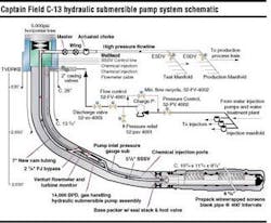
The main system machinery elements comprise a topside located electric motor driven power water charge pump and a gas handling HSP installed through a dry tree within Captain well C-13. The C-13 well was chosen for its location in the area of a small gas cap and therefore was likely to include free gas in sufficient quantities to prove the multiphase performance of the HSP.
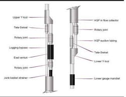
The HSP was installed and commissioned from the Captain WPP 'A' in June 1998. The well slot chosen, (C-13), was cleaned up by circulation and displaced to synthetic brine in preparation for the deployment of the upper completion string incorporating the HSP and Exal downhole monitoring equipment.
The double Y-tool completion was assembled over the rig floor from three pre-assembled sections to give a total stack-up length of 70 ft. On initial startup of the HSP, there was an early indication that the well was not as productive as was planned, possibly due to poor in-flow or high pressure drop over the sand screens or losses in the suction tail pipe upstream of the HSP.
The trial HSP operated very well under difficult conditions, and there were only minor changes to the pumpset caused by entrained solids within the pumped fluid. Extrapolation of the wear data indicated that the unit would have lost less than 5% of net production flow over a three-year run life. A decline in delivered flow of this amount could easily be recovered by increasing the supply of power water to the turbine.
The multiphase performance of the HSP had been well proven under the high gas levels experienced on C-13, and the unique ability of the pumpset to handle slugging flows had been demonstrated under field conditions. The new improved design of start-up thrust bearing would also eliminate any concerns over slow speed running or high numbers of start/stop cycles on future units.
Acknowledgement
Weir Pumps Ltd. and Texaco granted permission to publish this work. Angus Grant, Tom McConnell, John Dallas, Ronnie Graham, and Alex Lindsay of Weir, as well as Alan Morrison, Graeme Rae, and Sam Kashou of Texaco brought this project to conclusion. The late Mike Ryall (Weir) laid the foundation for the development of this new technology, and David Cohen (ex-Texaco) brought the trial to fruition. Expro North Sea Ltd. developed the downhole monitoring system.
Editor's Note: This is an updated and summarized version of OTC 13197.
