Mooring of floating platforms in deep water is a challenging effort calling for new solutions. A taut leg mooring system with polyester fiber ropes could reduce vessel excursions by a factor of 2-5. This may have significant implica tions for riser design and costs.
A three-year research program on taut mooring systems was recently completed, funded jointly by the Norwegian Research Council, oil companies, and contractors. It has focused on systems comprising synthetic fiber lines and anchors which allow for vertical loading, with research divided into four main areas:
- System design and costs
- Characteristics of synthetic fiber ropes
- Design and testing of anchors
- Installation and retrieval of mooring systems.
In deeper waters, traditional catenary mooring systems made from steel wire and chain become expensive, and also add large weights to the platform. Furthermore, stiffness provided by these systems decreases with water depth, leading to large horizontal offsets of the platform during extreme weather. This makes the riser solutions more expensive.
Taut mooring option
Deploying instead, a taut mooring system (TMS) with synthetic fibers could offer the following advantages:
- Lower weight
- Added stiffness, giving rise to horizontal offsets typically one quarter of those associated with a steel catenary mooring (SCM)
- Smaller footprint, and in contrast to steel systems, no potential hazard to subsea equipment should the line break and fall down to the seabed
- Easy handling due to the lower weight
- Cheaper than conventional systems in deepwater.
Synthetic fiber ropes have been used in offshore applications over the past few years. Several joint industry projects have also been launched to improve understanding of fiber rope moorings. Among them were the "Tethers JIP" completed in 1995, and the Norsk Hydro JIP, undertaken in 1995-96.
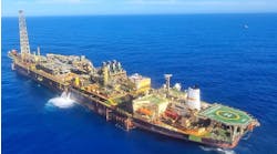
Recently a polyester mooring was applied to an FPSO in 1,420 meters water depth on the Marlim Field offshore Brazil. This was claimed to be the first application of an FPSO moored by synthetic ropes. However, the system is not a full TMS as vertical loads on the anchors are avoided by long bottom chain segments.
The main obstacles to use of a TMS have been uncertainties concerning the mechanical properties of the fiber ropes, use of anchors with a permanent vertical load and handling and installation of the fiber ropes. To address these issues, a three-year JIP was initiated by Norsk Hydro in 1996, called "Alternative Configurations and Materials for Mooring/ Anchoring." This has focused on the main obstacles to implementation of fiber ropes in deepwater moorings, with the following main activities being covered:
- Studies of fiber rope properties and behavior
- System design
- Suction anchors and vertically loaded plate anchors
- Transportation of large fiber ropes and installation of temporary and permanent mooring systems.
The research has received total funding of NKr 10 million, the sponsors being The Norwegian Research Council (NFR), BP, Elf, Conoco, Shell, Norsk Hydro, Saga, and Statoil. In addition, DSND, Brown & Root, Rockwater, Kvaerner Oil and Gas, and anchor manufacturers Bruce and Vryhof have made significant contributions to the studies with internal work.
Fiber rope studies
In leeward mooring lines, tension may approach zero during storm conditions. Furthermore, fibers can become exposed to compression during installation when small bending radii are imposed on the rope. The question to be answered is whether this compression causes significant reduction of breaking strength or fatigue properties.
Although there is little published data on the issue, there are indications that polyester fibers have a residual strength of 90-100% after being subjected to compression. For aramid, the figures are 20-30%. No residual fatigue life has been reported.
Another area of uncertainty relates to the effect of sand and clay particle ingress into the rope. This may cause abrasive damage to the rope when it is subjected to dynamic loads following contact with the seabed.
Yarn-on-yarn abrasion tests in a particle solution were undertaken to investigate potential abrasion damage to fibers in this situation. The goal was to ascertain the threshold particle size that caused damage. Initial tests employed a silica carbide particle (polishing powder) solution.
In general, the yarns tested in this solution experienced fatigue lives of a couple percent of the water control sample - the smallest particles creating most damage. Subsequent tests were performed in marine clay. Here results were even worse. We concluded that we had to consider real ropes to quantify the effect of particle ingress.
Medium-scale diameter ropes (20-30 mm) from three different manufacturers were then tested in various clay solutions, using a representative clay from eastern Norway. Each rope sample was subjected to 100,000 load cycles between 10 and 50 kN prior to the break test. After the cyclic loading, the specimens were tested to break. A strength loss of 20-40% was observed.
Microscope examinations were then performed to improve understanding of the degradation mechanisms occurring. For all samples, fluff was observed on the outside of the strands, particularly in the areas of contact with other strands. The same was also the case within a strand between the yarns. Examination with a scanning electronic microscope showed that clay was sticking to the individual fibers. Severe abrasion was also detected.
Analysis suggests that the outer fibers in a rope may experience a compressive strain of several percent when being spooled. When ropes are handled and installed, it is preferable to use drums and other equipment with small diameters. Current recommended practice is a minimum D/d ratio (sheave diameter over rope diameter) of 6-15.
Strength, stiffness
At 2,000 meters water depth, the hydrostatic pressure is 200 bar. This may impact the mechanical properties of the fiber rope. To this end, a literature survey was conducted, the conclusion of which was that an increase in stiffness and yield strength could be experienced. A more brittle fracture could also occur. However, the results of subsequent elongation tests at 200 bar hydrostatic pressure indicate that there is only a small effect on strength and stiffness of fibers subjected to high hydrostatic pressures.
TMSs work mainly through the elastic stiffness of the fiber rope, in contrast to wire/chain systems which function mainly on the basis of geometric stiffness. Accurate description of the elastic properties are thus very important when designing a taut mooring system. For the Norsk Hydro JIP, several full-scale ropes were tested under various mean loads, strain amplitudes, and frequencies. Results showed a smaller scatter, typically +/- 20% for load ranges of interest.
The present industry approach is to divide rope stiffness into three different terms: installation, drift, and storm. Installation is a load-controlled process and installation stiffness is not relevant to the design of a TMS, except for determining the early elongation of the ropes. Drift stiffness is used to calculate maximum vessel offsets. Dynamic loading of the lines is largely a displacement driven process, hence storm stiffness is used to calculate maximum line tensions.
When interpreting stiffness data, it is important to look at data for the load range that will be experienced by mooring lines up to a maximum of 40-60% of MBL. Recent rope data reveal that for the first load cycle to a certain load, the load-elongation follows the static curve (drift stiffness). The unloading follows a somewhat steeper curve (storm stiffness). From this, it may be concluded that the drift stiffness is useful in calculating the maximum line load.
System design, model test
For the JIP's system design, a semisubmersible drilling rig, the Bingo 8000, and an FPSO, the Kvaerner PS100, were considered. West Africa and Mid-Norway's Voering Plateau were the chosen model deepwater environments. For the West Africa conditions, the FPSO was spread moored. At Voering, it was turret moored. The drilling semisubmersible had spread mooring at both locations. Much larger dynamic loads were assumed for Voering conditions than for West Africa. 1,500 meters water depth was used as the base case for both investigations.
Polyester ropes were employed as the base case in both studies. However, evaluations were also made for aramid. Top and bottom segments of steel chain are used in the mooring lines (considered useful from a load point of view). Bending of the lines is avoided, tension in the leeward lines is better maintained and the ropes are kept away from the seabed. The length of the chain segments in the present study has been 150-200 meters.
Assuming the cost of the lines to be proportional to the total volume of the lines, optimization with respect to line costs was achieved by varying the line length and diameter. For Voering conditions, the optimum line angle (from vertical) was found to be around 45-50° for the semisubmersible and 60-65° for the floating production, storage, and offloading (FPSO) unit. The difference is due mainly to two factors:
- Different safety factors are used in the two cases (1.65 versus 2.53), reflecting the conditions for a drilling platform with disconnected riser and a production unit, according to DNV Posmoor rules 1996.
- The ratio between the mean mooring line force and the dynamic force due to platform motions is significant.
Compared to a catenary moored system, computation of maximum line loads is straightforward for a TMS. This is because the lines behave as pure springs at high load levels. For a CMS, dynamic load amplification due to drag locking is an important nonlinear and frequency-dependent effect which significantly influences the maximum loads. The fact that a TMS weighs much less than a CMS is valid. However, depending on the requirements for maximum allowable offset and pre-tension, the total vertical force on the floater may be similar for both mooring system types.
For traditional steel mooring lines, only extreme tension has been of concern. However, for synthetic ropes, minimum tension is also a factor as a large number of load cycles to low tension levels may cause compressive fatigue.
Polyester ropes are considered fairly robust compared to aramid ropes with respect to the number of low load cycles. For polyester ropes, 100,000 cycles crossing below 5% of MBL is the maximum recommended. For aramid rope the corresponding number is 2,000 cycles. To limit the number of low load cycles, the length of the line might be increased to raise the mean load level in the lines. Increasing the bottom chain length would also help.
Elasticity
Elasticity of polyester ropes may vary. As a basis, we have used unit stiffness over minimum break local ratio EA/ MBL = 31/.5. This represents a typical linearized average value for many ropes with realistic mean load levels. If this ratio is employed during design and the relative stiffness turns out to be different, the safety impact should not be severe. The reason is that pre-tension and mean environmental loads are not affected by the stiffness. For the Bingo 8000 in Voering conditions, a 10% increase in stiffness causes an approximate 2% decrease in the safety factor.
Model tests of a semisubmersible production platform with a ring pontoon and a 16-line mooring system were performed at the Marintek basin in Trondheim. Main objectives were to compare a TMS and a CMS and to check computations versus experimental values for motions and mooring line tension. Tests were performed with complete mooring systems in scale 1/100 and a full-scale water depth of 750 meters. Waves, current and stationary wind were included.
These tests confirmed the favorable offset characteristic of a TMS over a CMS. They suggest that extreme heave and pitch motions are not influenced significantly by the choice of mooring system, while the maximum horizontal offset is reduced from about 140 meters to 25 meters by replacing a CMS with a TMS. More surprisingly, under identical wave conditions, the relative damping level in surge emerged as higher for the TMS than for the CMS.
Mooring system cost analysis should take into account joint optimization of the riser and mooring design. For the platform used in the model tests equipped with 24, 6-in. risers, we find that the TMS solution will be less expensive for water depths beyond 500 m.
Soil conditions, anchors
For a CMS, the mooring lines are lying on the seabed without vertical forces on the anchor, even for the worst loading conditions. For a TMS, the mooring lines will be suspended freely in the water in all conditions. The JIP identified the new drag embedded plate, or vertical loaded, anchors as an attractive option that should be pursued. For mobile drilling units requiring multiple anchor handling systems every year, drag-in plate anchors were considered the most promising mooring concept, with suction anchors as a possible alternative.
The main advantage with this type of anchor is its holding capacity to anchor weight ratio, generally in the order of 100. This makes it light, easy to handle and store. From a geotechnical standpoint, it is also simple to estimate the capacity for a plate at a known position in the soil. The major uncertainty with this type of anchor is positioning accuracy and penetration depth. It may prove difficult, therefore, to predict the anchor's ultimate capacity.
To improve confidence in the design methods for the drag-in plate anchors, an onshore test prgram was undertaken focusing on soil/anchor interaction and simulation of the normally adapted offshore installation procedure. Testing was done in well documented sof tsoil conditions in southern Norway with models from Bruce's Denla and Vryhof's Stevmanta VLA ranges. Two different scales were employed, respectively around 30% and 40% of the prototypes. Fourteen tests of good repeatability were performed. In contrast to the manufacturers' predictions, negligible difference in performance was detected between the two anchors. Compared with the price of equivalent tests offshore. the trials were cost-effective - only NKr 2.1 million in total.
The drag-depth relation was verified by independent measurements. Performance ratio (pull-in force versus pull-out force) varied between 2.0 and 2.5 for the large anchors and 0.2-2.0 for the small anchors.
Installation, retrieval
Installation and retrieval of the drag-in plate anchors for temporary mooring, and of suction anchors for permanent mooring, were considered. The base case was an installation in 1,500 meters of water, again in West Africa/Voering, the primary differences between them being the size of the anchors. Studies on the installation and retrieval procedures were conducted by DSND and Brown and Root/Rockwater.
The main differences between installation of a TMS and a CMS anchor are:
- The fiber ropes must be handled with special care. The minimum allowable bending radius of the fiber rope during installation is a particular cause for concern. However, as bending is supposed to occur only a few times for each rope and is not preceded by any high loads in the rope, it is generally accepted that a minimum bending diameter of 6-15 times the rope diameter should suffice for polyester ropes. Installations have been performed using D/d ratios down to 3, suggesting that standard equipment can be used for the installation.
- Drag-in plate anchors combined with polyester rope are very light, with a potential for large horizontal drift off during lowering to the seabed. Furthermore, the drag plate anchors require a special installation procedure to penetrate to the require depth.
- Installation of the suction anchor in very deep water may cause problems with respect to vertical resonant motion during lowering to the seabed. As the length of the deployment wire increases, so too does the natural period of the anchor/wire system. The hydrodynamic added mass of a suction anchor with closed top end is around 1.5 times the enclosed mass of water of the anchor. This means that the hydrodynamic added mass may be 5-10 times the steel mass of the anchor. Ventilation through the top of the anchor may reduce these amounts significantly. However, precautions must be taken to avoid snap loads in the line. One way is to make a "soft spring" insert into the deployment wire to obtain a natural period well above actual wave periods. Another solution is to launch the anchors using a passive heave compensation system.
- Anchor rotation during installation must be controlled, possibly via an ROV thruster or by a line to a second vessel. In very deep waters, the last option may not provide sufficient force to counteract rotation.
- Positioning accuracy of the anchors is an important parameter which may add to the installation cost if set too strict. However, at 1,500 meters water depth, +/- 50 meters accuracy is not too difficult to obtain. With such an accuracy, the safety factor of the lines with respect to maximum loads will be typically within +/- 1%.
- The most important issue related to the installation of synthetic lines has been seabed contact. The question has been raised whether it is acceptable for a pre-installed mooring system to stay in contact with the seabed during installation or for a limited period.
The fiber rope tests suggest that contact with the seabed should be avoided at any time. This imposes definite restrictions on the installation procedures. However, practical techniques are available. All procedures require a more gentle handling of the lines than normal standard procedures for steel mooring systems. Also, precise control of vessel positions and deployed line lengths is essential.


