Harald Osvoll, Svenn Magne Wigen - FORCE Technology Norway AS
Operators have been using FPSOs for long-term field developments for a number of years. This type of production unit is either converted from an existing tanker or built from scratch to match a field’s reservoir characteristics.
The cathodic protection systems incorporated on the first FPSOs were based on a standard ship design, which used impressed current cathodic protection (ICCP) systems with four to six anodes with a relatively small shielding arrangement. These standard ship corrosion protection systems were based on dry docking and coating system repairs scheduled for every three to five years. As a result, not many of these FPSOs exceeded 10 years of continuous operation. Studies show that the expense of over protection can start from around year 10.
Comparing ICCP and sacrificial anode systems
An ICCP system includes rectifiers (two to four per FPSO) with built-in regulation systems, at least one reference cell per rectifier, penetrated into the hull, an ICCP anode for hull penetration, cables from rectifiers and regulation system to ICCP anodes and reference cells, and shielding around each single ICCP anode. Primary shielding is often a GRP arrangement around the anodes while secondary shielding is usually a coating system with thickness around 1000 μm.
An ICCP system requires a large safety factor, typically 50%, to cover for the risk of short-time failure of one or more anodes.
A sacrificial system includes galvanic anodes of AlZnIn alloy weighing from 100-200 kg each. The number required ranges from 300-600, depending on anode weight and required life. Each anode is welded to the structure at each of the inserts (two welds per anode). A sacrificial system does not include any active components.
FPSO CP design and simulation cases
In the early days of FPSO installations, ICCP design used an average fixed density, without considering possible coating breakdown during operation. CP design is now usually performed according to DNV or NACE standards. For the sacrificial anode design, this procedure is fully described by these or other equal standards. The ICCP design must include an estimation of shielding around each anode combined with its size to avoid critical potential on the hull’s coating.
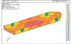
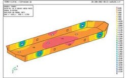
The potential distribution on an FPSO can be simulated by CP modeling tools such as SEACORR/CP program. Figures 1a and 1b present potential distribution on a smaller FPSO with a surface area of about 16,900 m2. Simulation of a classic ICCP ship design with only 4 anodes for end of life conditions is presented in Figure 1a, showing very negative potential (-1754 mV) close to shielding. The shield size for these cases is 11.3 m2. Figure 1b presents 20 anodes. The potential windows are from 219 mV with 20 anodes to 931 mV with 4 anodes.
null
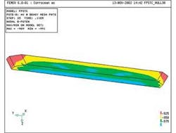
In Figure 2, potential distributions for end of life conditions are shown for an FPSO with sacrificial anodes. Its design life is 30 years and installed number is 611, each with net weight of 82 kg. The coating breakdown is 38%. The potential window is from -909 mV to -991 mV (an 82 mV difference).
These cases are based on a seawater resistivity of 0.2 Ωm. Resistivity is an important environmental factor directly influencing the protection capability for a system. A system with a given number of ICCP anodes requires a more negative anode potential to secure protection when there is an increase in resistivity, but also significantly increases risk for over protection.
Cost comparisons
The initial cost for ICCP anodes is less than for a sacrificial system, when electricity cost is excluded. Based on a cost per kWh of $0.1, the sacrificial system is less costly than the ICCP system. The source of electricity used on an FPSO may also factor in determining the cost of energy.
The following future cost elements for the ICCP system have not been included:
- Anode, shielding, and reference cell replacement may by required in 15-20 years
- CP monitoring and inspection of the system to secure optimum protection window and check of reference cells
- Any failure in single anodes has to be compensated by other anodes, until repair/replacement has been performed. This increases the risk for over protection.
Accept for over protection
The coating system has to be compatible with CP; risk for cathodic disbonding has to be within acceptable limits for the operational protection potential. The coating systems are tested based on an ASTM standard G8-90. This specification defines the test samples, test period, test potential level, and accept criteria. The test period is 30 days. The accept criteria defines the percentage of increased coating damage.
The coating system includes both the hull and shield. The hull coating close to the ICCP anodes may be exposed to potential levels significantly more negative than -1,150 mV for periods longer than 10 years.
For ICCP systems designed with shield dimensions resulting in a minimum potential of -1500 mV on hull, the performed coating tests for defining this accept level must be comparable with many years of exposure in the potential range of -1,150 to -1,500 mV.
The defined accept criteria for a typical hull coating system has been -1,100 mV, and by the latest version of DNV RP B401 has changed to -1,150 mV. There are design cases where the accept level has been set to -1,500 mV. This is based on coating testing.
The shielding coating system (which is typical from 800 μm to 1,200 μm) can be exposed to potentials significantly more negative than -1,500 mV. As long as the shield coating system is 100%, this will not be a problem. If damages occur, cathodic disbonding can be a major problem. Therefore, coating tests must include a realistic potential range and an acceleration effect covering several years of exposure to the actual potential levels.
For shield coating, it is extremely important to make a coating system 100% free from failures and damages. The operational potential window for any damages that the anode shield coating will be exposed to, will be from the potential level of the anode itself to the hull coating accept level. Any damage on the shield surfaces will be exposed to very high current density. The standard ASTM G8-90 tests are accelerated for coating disbondment and accept criteria are a given percentage of extended coating damage. The test potential is -1450 mV for a period of 30 days. In an actual ICCP case, part of the shield coating can be exposed to significantly more negative potential for the entire operational life of an FPSO. Therefore, it is very important that the shield coating tests include realistic potential levels and account for the possible long exposure to these negative potential levels.
The unit’s hull and shield coating systems can be exposed to significant negative potential for several years. When selecting -1,500 mV as the accept limit, it is very likely that the area around the shielding will be exposed to potential between -1,150 mV to -1,500 mV for at least 10 years. This has to be accounted for in any coating test.
Reproduced with permission from NACE International, Houston, TX. Paper 06107 presented at CORROSION/2006, San Diego, California.
