Reduces risk of pipeline blockage, optimizes production
Vincent Cocault-Duverger, Sylvain Denniel, Brett Howard - Technip Offshore UK
Pipe-in-pipe has become a well-established technology, providing high levels of passive insulation, in turn minimizing heat losses to the environment. This allows development of deep and ultra-deepwater fields with low reservoir temperatures, prone to wax or hydrate formation, but also of fields located remotely from topside infrastructure.
To meet increasingly stringent flow assurance demands, Technip has developed reelable pipe-in-pipe that incorporates active heating. The selected medium is electrical trace heating, already used on some offshore applications, and which can be adapted easily to existing reelable pipe-in-pipe systems.
Electrical heating allows the flowline temperature to be maintained above critical levels, and also allows controlled warm-up or extended cool-down periods. It thereby provides the field operator with a flexible means of optimizing production and reducing the risk of pipeline blockage. This flexibility can be enhanced through the inclusion of optical fiber technology for real-time temperature profile monitoring of the flowline.
Pipe-in-pipe trace heating and temperature monitoring systems can be divided into three main components:
- At the topside, the power supply is connected to a dedicated power control unit which regulates electrical power input within the system. A range of electrical fault detection features ensures safe operation. The temperature monitoring system control is linked to the power control unit, making control of the system easier and also providing real-time alarm signals
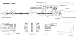
- Subsea power is provided typically via an umbilical that conducts electricity from the topside down to the subsea umbilical termination assembly (SUTA). The latter is connected to the near end of the electrically heated pipe-in-pipe (EHPIP) using standard wet-mateable power connectors and flying leads. The EHPIP’s pipeline end termination includes an ROV panel with ports for the connectors. A flanged bulkhead arrangement serves as the transition between the wet pressurized subsea environment and the dry atmosphric air environments in the EHPIP’s annulus
- The EHPIP itself, in which the electrical power input is dissipated in heat by Joule effect resistive heating. The optical fiber running along the pipeline returns the laser input signals from the control box to the same topside control unit.
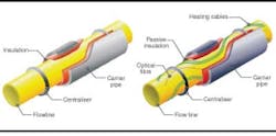
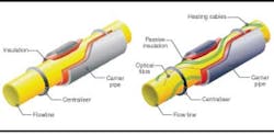
For both reelable pipe-in-pipe and the EHPIP, the flowline is insulated with high-performance passive insulation such as mineral wool, microporous silica, or aerogel. Polymeric centralizers are included typically at a pitch of 2 m to protect the lightweight insulation materials against crushing during reel-laying. The EHPIP also includes trace heating cables, packed in between the flowlines and the insulation for optimum heating performance. Optical fibers are another option, to provide a means of monitoring the flowline temperature profile.
The EHPIP’s trace heating system comprises a series of low electrical resistance copper core cables in groups of three, forming three-phase star connection circuits. At one end of the circuits, one phase of alternating current passes through each of the three cables. At the other end, the three cables are linked to form a star connection. Where they meet, the sum of the three current phases is nil, so a return cable is not required. Depending on the system’s heating demands, the number of sets of three-phase circuits normally ranges between two and four, with the option for one spare circuit.
Optical fibers are used for temperature profile monitoring. Among the available concepts, the distributed temperature-sensing method allows temperature data to be compiled at intervals along the entire fiber by analyzing back-scatter from a laser source injected into the fiber. An alternative technique is based on the fiber bragg grating principle, which determines temperature at specific locations by analyzing light reflected from etchings made in the fiber during manufacture.
Many existing pipe-in-pipe systems incorporate water stops at regular intervals - generally every 500 to 1,000 m along the pipeline - which are designed to limit flooding should the outer pipe suffer a breach. In the case of the EHPIP, a reelable water stop has been qualified, allowing the passage of cables without compromising sealing ability.
Technip’s trace heating system is designed to minimize non-productive shutdown times either through ensuring efficient warm-up operations, maintaining the line temperature above a critical wax/hydrate level, or by slowing the cool-down process. Due to a combination of the passive insulation and the location of the trace heating against the flowline wall, the linear power input to meet heating needs is relatively light compared with other systems, in turn allowing a lower total power input or heating over greater distances.
Potential applications for the EHPIP include:
- an alternative to a pigging loop for wax or hydrate mitigation
- very long tiebacks, with electrical power supplied if required at intermediate points via a dedicated power umbilical
- heating a steel catenary riser to counter temperature drop induced by adiabatic cooling
- acting as a complement to passive insulation systems during steady-state operation
- for use with a downhole electric submersible pump, with an electrical subsea switch module applied to divert the pump’s power supply to heating the pipeline in the event of shut-in
- heating short pipeline bypass sections.
The EHPIP’s linear heating needs are governed by: the targeted safe operation temperature and the environmental temperature; the pipe-in-pipe’s overall heat transfer coefficient (OHTC); flowline size and fluid content; and the purpose of the heating system.
To determine the required heating input, the operator must take into account the pipeline’s length, the available topsides electrical power, the number of three-phase heating circuits, and the electrical circuit components’ voltage and current limitations.
Technip’s calculations show that a wide range of insulation levels are feasible, according to the insulation material selected. Linear power needed to maintain the target flowline temperature depends basically on the OHTC. Power input for this mode of operation is typically only 15-30 W/m.
A PIP’s cool-down time is determined by the OHTC, which dictates the rate of heat loss, and by the size of the flowline, which governs the system’s thermal inertia. For analytical cool-down calculations, Technip only took into account flowline thermal inertia and content as the carrier pipe is close to the ambient temperature; furthermore, the insulation material contains little thermal inertia. By introducing only a small amount of heating power, the passive cool-down times could be extended appreciably.
Technip ran a series of tests investigating outlines linear heating power requirements for warming up the temperature of a water-filled flowline from 4 to 25°C; this is considered representative of the low point in a multiphase condensate line where water tends to collect during shut-in, and when hydrate risk is at its peak. The calculations applied to warm-up times of 12, 24, 36 and 48 hrs.
Results suggest a strong link between the EHPIP’s thermal inertia and the warm-up power requirements. OHTC also plays its part, but to a lesser extent. Targeted warm-up time also impacts power needs. In general, linear heat input is lowered by 40-45% through increasing warm-up time from 12 to 24 hrs. Power requirements for a 48-hr warm-up period are relatively low, but the savings will be offset by the potential production loss.
Having determined the linear power needs for different sizes and applications of EHPIPs, it is possible to establish a cable design and associated voltage/current parameters to achieve the performance target over a predetermined pipeline length.
For a set of cables with a given copper core cross-sectional area, power output depends on the level of circulating current. The maximum length that can be heated from one power source is governed by the voltage required to achieve the current level. For linear power requirements below 50 W/m, several tens of kilometers should be feasible via a single power source. As mentioned earlier, the inclusion of power feeding points throughout the line can magnify the achievable heated lengths. A power umbilical conducting electricity to remote locations would operate under a high voltage, low current configuration to mitigate longitudinal heat losses. Dedicated transformers would then be necessary to achieve the trace heating circuit’s required voltage and current.
Technip’s design and qualification program to date has included successful tests on a full-scale 8-in. EHPIP joint, including all components of the trace heating system, with T-piece and power connectors. Testing was conducted with the joint submerged in a water tank at a constant temperature of 4°C, with a flow loop circulating oil through the test piece.
Reference
Deep Offshore Technology Conference, Vitória, Brazil, November 2005.
