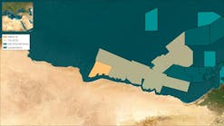
The complex nature of the multi-streamer marine 3D seismic surveys requires attention to detail to ensure all of the various components are assimilated correctly. By this means, the seismic objectives can be achieved efficiently. Besides the positioning of the vessel (usually by differential GPS or DGPS), there is the need to position all of the towed receivers in the deployed streamers. The positioning of the receivers is achieved by using a combination of positioning techniques.
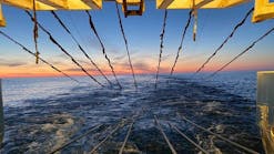
Wider and longer marine streamer arrays require close monitoring and navigational trucking to produce high-quality 3D data sets (Image courtesy of PGS).
At the front, tail, and sometimes in the middle of the streamers, braced quadrilateral networks are created combining relative GPS (rGPS), acoustic positioning, and magnetic compass data. These networks form the basis of the improved and continuous positioning now achievable.
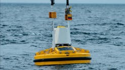
The towed gun arrays are positioned by means of rGPS, as are the tailbuoys at the end of each streamer. In-sea acoustic units and magnetic compasses are attached to the streamers at pre-determined points along their length. Receivers in between the networks are positioned based on a model of the streamer shape, the compass data, and its location on the streamer.
Due to the complex nature of multi-streamer 3D surveys, it is not unusual that some details are not addressed completely. However, the author has often seen marine 3D survey specifications which have omitted necessary critical details. These omissions, if left unresolved, could have affected the exploration company's stated 3D survey objectives, or significantly downgraded the quality of the survey.
By providing a set of guidelines and checklists, most users should be able to ensure that 3D seismic survey issues are addressed appropriately. Based on the user's requirements, some of the information could be omitted or used for other purposes, such as a basic 2D survey.
Survey guidelines
The guidelines are a series of 54 tables, which have been reviewed by several employees at each of three major seismic contractors. Other colleagues have offered their suggestions and comments. The equipment required and the expected performance of that equipment are described. Most of the values and other criteria suggested have been compared under actual 3D survey conditions and found to be acceptable. A tabular format was used to highlight the values and criteria suggested. Only brief comments follow some of the tables where applicable.
The tables should be used for reference and guidance in order to meet the objectives of the 3D survey. Users of the guidelines may wish to vary any of the values and other criteria suggested, due to commercial and operational considerations. The company may have to be prepared to accept a lower standard, due to time, budget, or other constraints. Also, changes may come about via negotiations to clarify or re-define possibly problematic criteria.
In the guidelines, not every table has every space completed. Some information will be supplied by the exploration company, and other information will be supplied and negotiated with the seismic contractor. However, the majority of the information provided in the tables should not have to be altered as the specifications detailed should suit most 3D marine seismic surveys.
Tables, calculations
An example of the information provided in the guidelines is in the accompan ying chart. The calculations in the chart are based on the bivariate probability of a point lying within an error ellipse drawn with semi-major and semi-minor axes ofsmax and smin. The correlation between the in-line and cross-line errors has been estimated.Range of variate
Using the error estimates for the in-line (sx) and cross line (sy) directions then smax and smin can be computed assuming a realistic value for the correlation (sxy). The correlation values are included to ensure all possible errors were considered instead of being assumed not to apply. The formulae are:s2max = 1/2 {sx2 + sy2 + [(sx2 - sy2)2 + 4sxy2] 1/2}s2min = 1/2 {sx2 + sy2 - [(sx2 - sy2)2 + 4sxy2] 1/2}The derivedsmax can then be used to calculate 95% (2.447smax). The above accuracies should be achievable for each source:- For the front (gun) float(s)
- For the first, middle and last trace on each streamer
- For each tailbuoy.
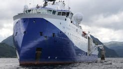
High resolution sruveys have tighter tolerances due to the smaller bin sizes created (Image courtesy of Schlumberger Geco-Prakla).
Sufficient redundancy should be incorporated in the network(s) design, to be able to achieve these results throughout the survey. Realistic a priori standard deviations (1s) should be used. The corresponding horizontal mid-point (HMP) accuracy would be 2.8 meters for the first and last common mid point (CMP), and 3.1 meters for the middle CMP for each streamer.
All of the tolerances and specifications in the guidelines support the values suggested in the above table. Due to the number of variables encountered in a marine 3D seismic survey the reader is encouraged to obtain a full version of the guidelines.
The suggested survey, navigation and positioning guidelines for 3D marine seismic survey specifications are considered to be practical or best practice values which are readily achievable. As much as possible the multitude of parameters involved has been described.
References
Calderbank, B., "Survey, Navigation and Positioning Guidelines for 3D Marine Seismic Survey Specifications" CSEG Recorder, May and June 1999; The Hydrographic Journal, October, 1998.
van Zeelst, J., "Further Considerations in Positioning of 3D Seismic Surveys," The Hydrographic Journal, January, 1991.
Naylor, R., "Positioning Requirements for Complex Multi-Vessel Seismic Acquisition," The Hydrographic Journal, October, 1990.
Author
Bruce Calderbank is President of Hydrographic Survey Consultants Intl. in Calgary Alberta, specializing in offshore survey, navigation and positioning consultancy worldwide. HSCIL has carried out 3D survey consulting assignments as the Client Navigation Representative for over 25 companies, while supervising a variety of contractors. This background and over 20 years of experience has allowed HSCIL to produce the guidelines.

