Lyle Finn
Horton Wison Deepwater
BPZ Energy has selected the Buoyant Tower design by Horton Wison Deepwater to develop the Corvina field offshore Peru. The design concept was selected because it is less expensive than the fixed platform alternative, and the fabrication and installation schedules were attractive. The fabrication contract was awarded in the fall of 2011, and the tower and topside are scheduled to be installed in 3Q 2012. The tower and topside are presently being fabricated in Nantong, China.
The Buoyant Tower falls in the category of a compliant structure. A compliant structure is allowed to move in response to environmental forces. Many offshore structures such as the guyed tower, compliant piled tower, spar, and TLP are compliant structures.
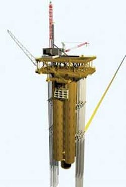
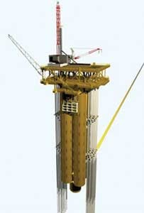
The Buoyant Tower is basically a cell spar that rests on the seafloor. The main body of the tower consists of four cylindrical tubes called "cells." The cellular approach is scalable, and designs for other locations and applications have been made with seven, nine, and 12 cells. In effect, the HWD Buoyant Tower design team has taken deepwater technology and applied it to shallow water.
The tower supports both drilling and production. In the BPZ case, oil and gas are exported to an FPSO. A tender vessel will assist in drilling. The buoyant tower concept can be designed to support full drilling and processing, depending on the client's needs. For the BPZ design, the wells are supported by conductor pipes that are self-standing on the seafloor, and supported laterally by guides on the side of the tower. Top tensioned risers are also possible and may be the preferred option in the deeper end of the design's water depth range.
Tower fabrication
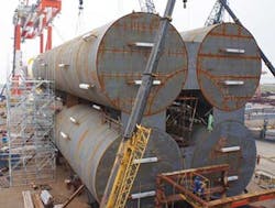
In some offshore arenas, the Buoyant Tower is cost-effective for developing shallow-water fields because both the fabrication and installation costs are reduced. The fabrication cost is reduced because of the simplicity of the cellular components of the hull. The cell fabrication of the BPZ tower was completed in about three months by pressure vessel shops in the Nantong area. The cellular construction proceeded rapidly in part because many of the welds (about 80%) can be done with machines (sub arc and track welders). The cell segments then were transported to the assembly site where outfitting, stacking, and assembly is proceeding and expected to take another three months.
Tower installation
The fabricated tower and the topsides will be loaded on a heavy-lift vessel for transport to Peru. Near shore, the heavy-lift vessel will submerge to allow the tower to float off. The topside is supported on a truss system that will keep it above the water during tower float off. Once the tower is floating in the horizontal position, it will be towed to near the final installation site where it will be upended using proven procedures. Magnetite fixed ballast material will then be pumped into the bottom end of each cell to further stabilize the tower and increase its draft.
The truss system on the heavy lift-vessel supporting the topside extends over the side of the vessel. The floating hull will then be pulled into the gap in the extended truss system and secured lateral to the vessel. The topside will be skidded outboard of the heavy-lift vessel and positioned over the tower. The tower will be deballasted, causing it to rise and mate with the topside. Further deballasting will lift the topside clear of the supporting truss system. The tower with its topside will then be towed to the installation site and set on bottom by deballasting. Mooring lines are not required to keep the tower on station, so the entire installation proceeds rapidly.
The Buoyant Tower is held in position by a suction can foundation (SCF) located at the bottom end of the main cells. During installation, this can is forced into the seafloor. The necessary forces can be generated by ballasting some of the tanks in the tower and allowing the tower weight to push the can into the soil. An additional suction embedment force can be generated by lowering the water pressure inside the SCF. Once the SCF fully penetrates and the inside is filled with soil, the vertical bearing capacity increases substantially. The downward load on the SCF is then reduced for the long term.
The SCF has three main functions:
- To provide lateral support to the tower and ensure it stays in position
- To provide vertical support with minimal long-term settlement
- To permit the tower to rotate in response to the environment.
The tower is held upright by the buoyancy of the cells, and thus the foundation is not required for tilt stability. Like a spar, the center of the buoyancy is above the center of weight so the structure is unconditionally stable. To be compliant with the wave forces, the tower must be able to dynamically tilt as the wave pass through. The rotational restraint of the SCF is small relative to the moment of the wave forces.
The calculated lateral and vertical load capacities for the SCF are adequate to keep the tower on station. A detailed ABAQUS finite element model of the soil and SCF is used to confirm the load capacity calculations. A series of model tests further confirms that the SCF will allow the tower to tilt in response to waves and at the same time keep the tower from excessive lateral or vertical displacement.
The wells are supported by conductor pipes that are jetted, drilled, or driven into the seafloor. These conductor pipes are supported laterally by a series of guides placed along the length of the tower. Drilling is done by a rig on the top deck of the topside, similar to fixed platform drilling. The BOP is located below the drilling rig. Because the wells are some distance from the center of the tower, there is a small amount of relative vertical displacement between the wellhead and topside as the tower tilts in response to the environment. To accommodate this relative motion, a short, flexible jumper between the wellhead and the manifold is required.
Applicability
Design studies confirm that the HWD Buoyant Tower concept is applicable in water depths from 50 to 260 m (165 to 853 ft). The tower motions improve with water depth and the design becomes more efficient. However, in the upper end of the water depth range the costs of the tower increases to the point where floating concepts are more efficient.
SCF model tests indicate that this foundation type is applicable in areas with milder environmental conditions. This includes the non-cyclonic event belt on both sides of the equator, and other milder environmental areas such as offshore Peru, Brazil, and West Africa. Studies for towers in the Mediterranean and Caspian seas show the concept is also feasible in these areas. Extension of the design to harsher environmental areas is under study.
