Rigless, screenless completions solve sand control problems in two offshore fields
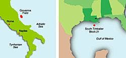
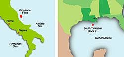
PART I: This is Part I of a two-part series. Part I focuses on successfully applying the screenless completion technique to a newly drilled sidetrack in the Gulf of Mexico where sand produc-tion has historically been problematic. Part II will focus on its use to restore production in Adriatic Sea wells, where sand production problems have negatively impacted reservoir productivity during the past several years.
By Claud Riddles
J.M. Huber Corp.
Andrew Acock,
Steven Hoover
Schlumberger
A novel screenless completion technique provides a cost-effective alternative to conventional sand control methods, reducing completion costs and enhancing reservoir productivity while maintaining wellbore accessibility.
A correctly engineered and installed screenless completion will:
- Control formation sand production and fines migration
- Increase hydrocarbon production rates and reserves
- Eliminate a rig-based operation and screens with associated hardware.
As the name implies, the screenless completion controls sand production without screens, avoiding the limitations and risks associated with screens. These include possible induced skins and reduced productivities, as well as the costs of additional downhole hardware and the potentially frequent repairing or replacing of plugged or failed screens. Because these completions can be performed without a rig, they eliminate the added costs and risks associated with rig-based operations.
Eliminating the need for a bridging mechanism created by a conventional annular gravel pack between a screen and casing results in enhanced conformance control and a fullbore completion. Full wellbore access presents broader well logging, reservoir management, and recompletion options down the road.
Well enhancements
Screenless completions not only reduce costs and risk, but they also promote enhanced sand-free hydrocarbon production by combining proven techniques, including perforating, consolidation, and fracturing with proppant-flowback control. Screenless sand control can be used as a primary completion for new wells or sidetracks that are expected to produce formation sand. For existing wells, this technique offers a cost-effective sand-free remedial operation for the following:
- Wells without gravel packs
- Sand control completions with eroded or corroded screens and/or plugged gravel packs
- Existing wells with bypassed zones, in which circumstances prevent screen installation.
Screenless completions reduce costs, mitigate risks, and promote enhanced sand-free hydrocarbon production by combining proven techniques that include some or all of the following:
- An optimized perforating strategy
- A consolidation procedure
- A tip screenout (TSO) hydraulic fracture treatment
- Proppant flowback control
- A plan for controlled flowback and produc-tion drawdown.
For new wells, the screenless completion technique begins with a perforating strategy that includes optimizing factors such as perforation phasing, interval length, hole size, and shot density. Perforation phasing depends upon whether in situ stress directions are known.
Whether the well is vertical or deviated determines the perforated interval length. Shot density and charge type are selected based on the pressure drop desired during fracture fluid injection and hydrocarbon production.
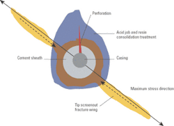
To prevent sand production, a TSO fracture that contains the appropriate proppant and flowback control additives should cover all of the perforations. Therefore, entrance hole diameters must be less than the propped fracture width.
If applicable, the next step of the screenless completion process involves in situ consolidation, which entails pumping a chemical system, usually an organic resin, through the perforations and into the formation. Used for many years to consolidate weak formations, resins bind the formation sand grains together and increase the formation strength around perforations, thus preventing a near wellbore screenout during subsequent fracturing operations.
If there is a gravel pack in an existing well, the treatment can be used to consolidate the gravel in the annulus to ensure that the perforations remain open. The success of this type of consolidation treatment depends strongly on the chemistry of the fluids used in each stage of the treatment as well as physics and fluid placement.
A hydraulic fracture treatment is the next phase of the multi-step process. A highly conductive fracture that is both short and wide is a requirement in laminated, poorly consolidated sandstone formations to connect the layered sandstones, bypass any near wellbore damage, and create a flow path for hydrocarbons from the reservoir to wellbore. To accomplish this, a TSO fracture must be achieved to create a favorable skin and a highly conductive path for hydrocarbon flow. In addition, the large surface area of this fracture type makes it an effective filter for preventing sand production. For example, a 45-ft long, 22-ft high fracture has a surface area of 3,960 sq ft compared to the same height gravel pack's 34-sq-ft openhole flow area.
When implementing a screenless completion, it is imperative that the formation sand and the placed proppant remain inside the fracture because no screens are present. Proppant flowback-control additives are employed for this purpose. The PropNET additive from Schlumberger creates a physical, rather than chemical, mechanism to stabilize and reinforce the proppant pack with randomly oriented fibers. Thus, its use does not require specific temperatures, pressures, or shut-in times during fracturing operations.
The carbon fibers are mixed with the proppant before pumping downhole into the well and inducing fracture. Field experience has shown that the fibers allow immediate and rapid fracture flowback. This is attributed to the reinforced network built, interlocking the proppant grains together. Because the fibers are made up of inert materials, they are compatible with all fracturing fluids.
In November 2000, J.M. Huber became operator of the South Timbalier Block 21 field offshore Louisiana. A sidetrack opportunity was identified shortly later in the No. 48 well to recover updip attic oil reserves in the D-10 Upper Miocene sand. After drilling directionally and logging the well, a clean, oil-and-gas bearing 22-ft sand extending from 11,772 ft to 11,794 ft was identified by resistivity and gamma ray induction logs and confirmed with side wall cores.
The D-10 sand is a fairly clean, Upper Miocene compartmentalized sandstone formation with an average porosity of 28% and 100-500 md permeability. A strong aquifer is present; reservoir pressures of about 5,800 psi (0.511 psi/ft) have been measured. In general, the Gulf of Mexico's Miocene formations have low unconfined compressive strengths (less than 1,000 psi) and typically require some method of sand management. In this case, sand control was deemed necessary because of a history of sand production in the South Timbalier field, as well as the vertical No. 48 well's previous D-10 sand producing experience.
Sidetrack completion
Originally drilled in 1963 by Gulf Oil, the No. 48 was a caisson with a well guard and could not support interventions from the structure. A standard gravel pack was planned for the sidetrack well with a 5-in. liner, 20/40 gravel, 2 3/8-in. screens, and 2 7/8-in. production tubing.
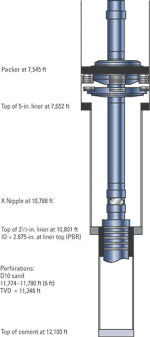
The 40° hole angle and pressure depleted zones above the target sand caused the 5-in. liner to become differentially stuck above the target setting depth, requiring that it be cemented in place. A 3 1/2-in. liner was then run in the 6-in. open hole to a 12,100-ft total depth. The planned gravel pack completion was no longer suitable due to the limited internal diameter of the 3 1/2-in. liner.
Studies undertaken
The joint Huber/Schlumberger completion team selected a through-tubing screenless completion that incorporated a customized perforating design, a formation consolidation procedure, a tip screenout fracture treatment with proppant control additives, and a careful monitoring and flowback plan. While the team knew that screenless completions offered many advantages, experience had raised questions regarding the prospects for their successful application in the GoM.
An analysis of job failures led to the following conclusions regarding the use of screenless sand control in this area. Studies undertaken of previous unsuccessful procedures confirmed that if any one of the necessary steps previously mentioned was misapplied, the chances for job success dropped dramatically. To achieve success, the strict guidelines regarding the multi-step process must be followed. There-fore, the key elements - perforating, consolidation, tip screenout fracturing, and proppant flowback control - were carefully planned and implemented to ensure a successful screenless completion.
Redesigned completion
A polished bore receptacle was designed for the top of the 3 1/2-in. liner to allow a seal assembly to be strung into it. The redesigned completion had a 7-in. packer assembly with 2 7/8 in. tubing above and below it to allow for a through tubing fracturing operation. Tubing movement calculations ensured equipment stability and a fracture simulation determined safety limits during the fracture stimulation treatment.
A jackup rig was used to accommodate the coiled tubing (CT), pumping equipment, and wireline unit. The completion involved four phases:
•Drilling out the cement plug in the 3 1/2-in. liner
•Perforating followed by CT acidizing and resin consolidation
•Tip screenout fracture treating incorporating proppant flowback control
•Cleaning out using CT.
Perforating strategy
The perforating strategy called for a minimum number of shots to prevent leaving a single perforation unprotected from sand production. A too-small casing entrance hole diameter could prohibit a proppant fracturing operation, yet one too large could allow proppant flowback after the treatment. To meet these requirements and maintain productivity, a 0.33-in. entrance hole diameter was deemed optimum. In addition, perforating shot density was six shots per foot.
Nodal analysis determined a 6-ft optimal perforated interval length (of the 22-ft zone), which would provide 400-b/d production rates with less than 100 psi drawdown. Also, the team selected zero-degree phasing to ensure all of the perforations were connected to the fracture and prevent perforations from remaining unprotected by the proppant.
Consolidation treatment
The next critical step was to apply a consolidation treatment to the zone around the perforations. The model showed that the perforation
would penetrate 17 in. into the formation and form a crushed zone around the perforation tunnel that transitioned outward into virgin rock.
The team was concerned that proppant might flow out of the perforation tunnels, with the risk that produced sand could follow. This possibility established the need to consolidate the area around the perforations. They selected a furan resin, which would provide suitable consolidation and, using CT, could be placed effectively throughout a short perforated interval.
Fracture treatment
Although resin may have been sufficient in preventing early sand production, it has been shown to reduce the permeability of the nearby formation. Therefore, a fracture treatment was needed to connect the formation to the wellbore and bypass near wellbore damage. A 20/40 stress-cured resin-coated ceramic proppant (RCP) was selected because of the stress environment of 8,000-psi closure pressure. Stress-cured RCP requires that closure pressures bond grains together, also facilitating CT cleanout after treatment.
A low-guar borate crosslinked fracture fluid was selected as the optimal, most compatible fluid with this reservoir's produced hydrocarbons. Also, the need to prevent proppant flowback after the fracture treatment required that a 1.5% fiber additive be used throughout the proppant stages. The soft rock environment necessitated a TSO fracture design because screening out at its tip would create a short, wide fracture.
The TSO fracture was performed as designed from a stimulation vessel, followed by a slowdown schedule near the end to avoid overflushing and high treating pressures. At the treatment's conclusion, 13,204 lb of proppant had been pumped with 9,096 lb placed in the perforations.
Results
Controlled flowback to surface and subsequent testing immediately after the fracture treatment measured initial rates of 535 b/d of oil and more than 4 MMcf/d of gas at a 3,700-psi flowing tubing pressure. Production was monitored carefully, stabilizing at about 500 b/d of oil and 2.5 MMcf/d of gas at a flowing tubing pressure of 3,500 psi.
When matched with Nodal analysis, a slightly negative skin and 200-md permeability resulted. When analyzed, the well had produced for more than a month without any indications of sand production. The success of this treatment is attributed to teamwork, quality engineering, a combination of best practices applied worldwide, and a willingness to try a new approach.
Acknowledgment
The authors acknowledge J.M. Huber Corp.'s Offshore Business Unit in Houston, Texas.
