UV disinfection improves EOR Meets other functions as well
John McClean
ETS
One of the oldest and most widespread techniques for enhanced oil recovery is well flooding by injecting water downhole. Water is injected into the reservoir to pressurize and displace hydrocarbons towards the producing wells. Injection water also is used in water-storage operations in offshore and remote locations.
The injection water quality is critical to EOR success, as the displaced oil must flow through porous rock structures. Treatment of water for injection is multi-stage, with filtration to remove solids and de-aeration or oxygen stripping to reduce the oxygen content. Ultraviolet (UV) light used as a penultimate stage ensures that the water sent downhole is free from microbial contamination without the use of chemicals that might affect flood performance.
The problem
Seawater used for offshore well injection contains a variety of microorganisms. Some of these lead to corrosion and scale downhole, while others form slime. Many species can survive in either oxygen rich (aerobic) seawater, or in the oxygen starved (anaerobic) environment below ground.
Aerobic bacteria can convert iron from the ferrous (Fe2+ ) to the ferric (Fe3+) state, and produce ferric hydroxide (Fe (OH)3), which is highly insoluble and causes formation damage. Iron oxidizing bacteria can be a slime forming species that form mats of high-density slime that cover surfaces. In a well, they shield corrosion forming bacteria from chemical bactericides and plug pores in the matrix holding the oil.
Anaerobic species such as sulfate reducing bacteria, (SRB) can convert sulfate or sulfite that occurs naturally, or present in a variety of drilling muds into hydrogen sulfite (H2S). When combined with iron, iron sulfide scale is formed that is costly to remove. In addition, SRBs can cause pitting corrosion of steel, and elevated H2S increases the corrosiveness of the water to increase the possibility of hydrogen blistering, sulfide stress cracking, and can lead to sour oil which requires sweetening.
UV systems usually are installed in the process after the filtration of the seawater to remove suspended solids. The filters can often be a source of microbial growth, so the UV equipment should be installed post filtration.
UV light has no residual effect, so periodic disinfection with sodium hypochlorite or other biocides still is required. The advantages of UV include reduced chemical use, space saving, and improved operator safety.
How does UV work?
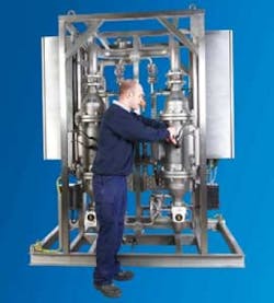
UV light is a physical, non-intrusive process with broad industrial and municipal uses. Systems comprise of 316L or Duplex steel chambers that contain high-power UV lamps. Wiping systems keep the quartz sleeve free of fouling. A UV monitor camera ensures proper disinfection, and systems usually come in duty/standby configuration. For offshore use, modular skid mounted packages are built and tested before installation.
UV light between 200 nm and 300 nm passes through the water and is absorbed by DNA in the nucleus of organisms in the water. When the UV light is absorbed, the DNA becomes so damaged that the organism is instantaneously rendered non-viable. Normal cell function ceases; the organism cannot replicate, respirate, nor assimilate food. Once viability ceases, the colony quickly dies.
No organism can survive UV light. Many species are increasingly tolerant to chlorine; emerging pathogens such as Cryptosporidium and Giardia demonstrate high chlorine tolerance. UV light has been demonstrated to be effective against SRB species, and is non-selective; any micro-organism in the seawater is deactivated.
UV systems are sized based on three main factors: Flow rate, water quality, and the challenge organism. Computational fluid dynamics (CFD) models are used to design and size UV systems.
The flow profile is a result of chamber geometry, flow rate, and the turbulence model selected.
The radiation profile is developed from inputs such as water quality, lamp type, and the transmittance and dimensions of the quartz sleeve.
Proprietary CFD software simulates both the flow and radiation profiles. Once a 3D model of the chamber is built, it is populated with a grid or mesh that comprises of thousands of small cubes. Points of interest, such as at a bend, near a sleeve surface, or areas near the wiper mechanism, get a higher resolution mesh. Other areas in the reactor use a coarse mesh. Once the mesh is produced, hundreds of thousands of virtual particles are fired though the chamber. Each particle has variables of interest associated with it, and the particles are collected after they exit the reactor. Discrete phase modeling produces delivered dose, headloss, and other chamber specific parameters.
When modeling is complete, the resulting system is validated using a third party to provide oversight that determines how close the model is able to predict system performance. Validation uses non-pathogenic surrogates such as T1 phase or MS-2 to determine the reduction equivalent dose (RED) ability of the reactors. Most reactors are validated to deliver 0.5 log to 6 log reductions of SRB species within an envelope of flow and transmittance.
In-line UV systems are simpler to install and occupy less space, which is critical on an offshore platform.
In addition to injection water for enhanced oil recovery, UV systems are used offshore for the disinfection of drinking water and for the non-chemical disinfection of wastewater prior to discharge.
Case study No.1
The Eldfisk oilfield is near Ekofisk in the North Sea, in sea depth of 200-225 ft (61-67 m). The original Eldfisk development consisted of three facilities. Eldfisk B is a combined drilling, wellhead, and process facility. Eldfisk A and FTP are wellhead and process facilities. In 1999, a new water injection facility, Eldfisk E, was installed. The facility also can supply injection water to Ekofisk K. The facility uses horizontal injection wells, injecting into a reservoir between 8,000 and 8,700 ft (2,438 and 2,652 m).
The UV plant treats 4,000 cu m/hr, or 25 MMgal/d, and is the largest downhole injection facility in operation. The system comprises of duty and standby units, and was supplied by atg in the UK. It is modular, and has been in operation for more than 10 years.
Case study No. 2
The Troll platform, a concrete deepwater offshore natural gas platform in the Troll gas field, is the tallest construction that has ever been moved to another position, relative to the surface of the Earth, and is among the largest and most complex engineering projects in human history.
Standing at a height of 1,400 ft (423 m) and weighing over 1.2 million tons, the Troll platform depends on a crew of over 350 engineers to draw natural gas from over 40 gas fields on the seafloor.
To keep the Troll crew safe from infectious waterborne diseases such as Legionella and Cryptosporidium, ETS sister company atg designed and supplied two high-specification duty-standby ATEX-certified systems for operation in Zone I & II hazardous areas.
These units are configured as duty/standby to ensure that the crew has safe drinking water.
About the author
Jon McClean is president of ETS, LLC, and has more than 20 years experience in the industry. ETS is a USA manufacturer of UV disinfection equipment for a variety of applications, from offshore downhole injection, to ballast water disinfection on cruise liners, to keeping swimming pool environments free from contaminants.


