Ultra-deepwater riser choice requires careful analysis
HRT v. SCR
Vincent Alliot, Jean-Luc Legras and Dominique Perinet;
Stolt Offshore SA
One of the main challenges associated with deepwater field development is the riser system, which transports the production fluids from the seabed to the floating production facilities. Initially, the flexible risers used on shallow-water fields were employed in deepwater field developments. As production heads to water depths in excess of 1,000 m, however, a small number of riser concepts can meet the extreme challenges. The two main riser solutions for deepwater fields are hybrid riser towers (HRT) and steel catenary risers (SCR).
In 2001, three HRT systems were installed as part of the Girassol development offshore Angola.
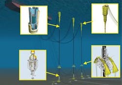
The HRT concept bundles a number of riser pipes around a core pipe. They are fabricated and assembled onshore, prior to being towed to the field. Once at the field, the riser is upended and connected to the seabed via a pre-installed suction anchor. Finally, the top of the HRT, which is at an optimum depth to minimize the effects of strong wave and current action, is connected to the floating production facility through a series of short flexible pipes.
The concept of a bundled vertical riser has its origins in the Gulf of Mexico, where in 1988, Placid installed a riser bundle on Green Canyon block 29, and in 1994, Enserch re-deployed the same riser on Garden Banks block 388. In 2001, three HRT systems were installed as part of the Girassol development offshore Angola.
The SCR concept is an extension of a steel flowline that connects to the floating production facility. An SCR is required for each flowline.
The SCR is installed using pipelay technology with offshore welding, which is a critical issue. The first SCRs were installed as export risers on the Auger development in the GoM in 1994. Since then, a number of SCRs have been installed, mainly in the GoM, with some in Brazil. In 2004, the first West African SCRs were installed and connected to an FPSO on the Bonga field offshore Nigeria.
Each of these riser concepts has its positive and negative aspects that may not be appreciated fully at the time of the riser concept selection. The lessons Stolt Offshore learned from a range of deepwater projects in West Africa involving each of these riser concepts, has been invaluable. Projects include Girassol (HRT for Total), Bonga (SCR for Shell), Erha (SCR for ExxonMobil), and more recently, Greater Plutonio (HRT for BP). Stolt has used the results from its riser assessment to optimize the selection process and propose the best business solution to the operators of future field developments in deep and ultra-deepwater.
The HRT consists of a vertical column made of one or several pipes used for transporting fluids and/or providing mechanical stiffness to the structure. A top buoyancy structure and/or distributed buoyancy elements along the column stretches this vertical column. The interface with the seabed is static and consists of an anchor base. The anchor base connects to the riser column using a mechanical device designed to absorb the dynamic inclination motion of the tower (taper joint or flex joint).
At seabed level, vertical risers and horizontal flowlines interconnect through spools and diverless connections (typically standard flanges with the Matis connection tool). The interface with the surface process facilities is made through short flexible dynamic risers engineered to ensure the continuity for fluid transport and absorb heave motion of the production unit. The HRT incorporates additional facilities such as an umbilical support arch or other devices required by the field operation.
The three HRTs installed at the Girassol field were all fabricated onshore, towed to the field, and then installed prior to the arrival of the floating production unit.
The riser tower Placid first used in the GoM was more like a drilling riser, as it was made up of individual joints, which were installed using the drilling derrick onboard the floating production semisubmersible. The three HRTs installed at the Girassol field were all fabricated onshore, towed to the field, and installed prior to the arrival of the floating production unit. This is a significant advantage, as it allows more flexibility and less risk to the overall project development schedule.
SCR system
The SCR is a single pipe suspended from the surface support facilities in a catenary shape, which lies on the seabed and either continues directly into the horizontal flowline or connects to it mechanically. Interface with the floating production unit consists of a hang-off structure and a flex or taper joint to absorb the dynamic moment variations generated by the motions of the floating production unit. The interface with the seabed is dynamic, as the touch down point (TDP) can move both axially and laterally along the seabed.
An anchor system can also stabilize the pipe axially and cancel ratchet effects resulting from cycling expansion loads along the pipe. This interaction creates a fatigue-sensitive zone that often requires special design, material selection, and fabrication processes. SCRs are fatigue-dominated structures, with the hydrodynamic loads from waves and currents, including those generated from vortex induced vibrations, playing a significant role in the design and subsequent fabrication of the SCR.
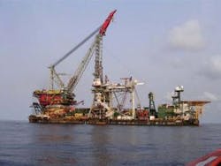
Generally, SCRs are produced offshore using a specialist pipelay ship fitted with a j-lay installation spread. SCRs are installed once the floating production unit is in place. Installation involves a complex handover operation between the pipelay ship and the floating production unit, where vessels are working in close proximity. It is possible to consider pre-laying the SCRs; however this requires a significant amount of space on the seabed, which may not be available within the mooring pattern of the floating production unit, particularly when a large number of risers is involved.
Parameters determine system
Field development parameters produced by the operator generally take precedence in the evaluation process to select and propose a dynamic riser system.
Such parameters include:
- Well stream fluid characteristics such as pressure and temperature at the wellhead, fluid impurities (H2S, CO2, and sand), and viscosity in combination with the water depth, which impact the requirement for flow assurance, corrosion, and erosion protection
- Enhancement and protection requirements to define flow rates for water, gas, and chemical injection in the reservoir and the diameter of the required risers
- The shape and configuration of the reservoir to drive the well and completion plans for the overall field development. In turn, this drives the production facilities and the subsequent field layout and subsea architecture
- Subsea and surface operating philosophy of the operator (cluster or daisy chain arrangement, pigging philosophy, and warm-up, start-up, shutdown, and contingency procedures) that impact the choice of the dynamic riser system. Plans for future field extension also have to be integrated in the decision making process
- Metocean and seabed conditions and design life are major design, fabrication, and installation engineering parameters that drive the choice for dynamic riser systems.
The HRT is installed prior to floating facilities installation, which allows earlier schedule for first oil.
HRT is subject to little fatigue damage when in operation. The surface towing operation mainly generates the fatigue. The Girassol experience proved that numerical models developed to assess this fatigue are reliable and accurate. Fatigue occurs along the lower part of the tower during towing occurs in the lower part of the tower, as opposed to during operational conditions, when most of the fatigue damage is at the taper joint between the riser bundle and the buoyancy tank. Fatigue considerations impose little constraint on the fabrication process. On the other hand, SCR fatigue damage dominates all aspects of riser integrity, dictating the choice of material for the riser structure and driving the high quality welding requirements for the fabrication process. The fatigue damage is driven by the dynamic response of the SCR, where the hydrodynamic loads from waves and current, combined with the complex stresses induced from vortex induced vibration, produce significant fatigue loading.
The fatigue-sensitive areas of the SCR are the upper sections, where the riser connects to the floating production unit, and the TDP where the riser contacts the seabed. Fatigue tests may be required to confirm and validate engineering studies and selection of S-N curves. Installation operations can induce some fatigue damage in the pipe structure depending on the installation spread motion and interface loads between the SCR and installation spread.
In addition, depending on the submerged weight of the coated pipe and support surface conditions, the dynamic response of the SCRs can induce compression loads at the sag bend, which design codes do not consider.
Seabed interface
The interface between the HRT and seabed involves more components than the SCR solution (i.e., riser tower base and its flexjoint, spools to connect to the flowline system, and diverless connection). This impacts the fabrication and installation scope; however, the techniques associated with these components are all field-proven, and engineering associated to them is straightforward. The interface between the HRT and seabed is not considered critical or difficult to resolve. Generally the HRT solution leads to a simpler field layout compared to an SCR option.
The interface between the SCR and seabed, however, can raise some concerns because the consequences of the technical issues associated with TDP excursion and embodiment/trenching are not fully understood in the long term. Although large-scale tests and studies have been performed on the subject, they have not been validated by field experience. In addition, phenomena such as longitudinal ratchet motion of the flowline due to cyclical thermal expansion can induce loads on the SCR that are not acceptable. This has resulted in the use of anchors to secure the long-term stability of the riser and flowline on the seabed.
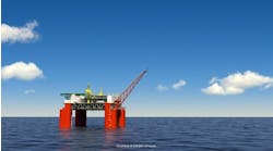
The HRT creates lower loads on the hang-off balcony of a floating production unit. This represents a major advantage in the case of a TLP or semisubmersible. Because the HRT is a vertical self-supporting structure, the top tension transferred to the floating production unit can be reduced by several thousand tons. This impacts the mooring design and the payload capability of the floating facilities. The HRT flexible jumpers also can connect to the FPSO turret for harsh environment applications.
SCRs are sensitive to dynamic motion of the surface facility and, therefore, the hang-off balcony must remain as close as possible to the center of gravity of the floating structure.
Also, special devices such as riser monitoring, gas lift, heating systems, methanol injection line, or any system required by the operator to facilitate oil recovery are easily integrated into the HRT structure, but complicate the field architecture if SCRs are being used.
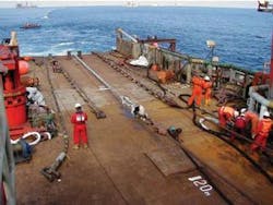
SCR fabrication generally is done offshore from a pipelay ship. The interface between the SCR components and the installation equipment requires careful consideration and management to ensure that the integrity of the riser is not compromised. Any contact point between the two systems must be analyzed to check compatibility of dimensions, static and dynamic loads, and material. The quality of the welding performed offshore must be to the highest standard to control fatigue damage to the SCR.
HRT fabrication generally is performed onshore at a dedicated fabrication yard. The onshore environment offers conditions that allow easier quality control of the work performed. No specialist fabrication skills are required for the HRT. As a result, it is possible to use suitable fabrication facilities in the country of the field development, maximizing the benefit to the local workforce and community.
Installation
SCR and HRT installation are considered critical operations and expose the project to some risk. In the case of the SCR, the overall installation, which can often be seen as an extension of the pipelay operations, takes longer and is more complex due to the combined fabrication/installation activities and the higher probability of an undesired event, although the consequential damage is limited to only one riser. SCR requires mobilization of a sophisticated installation spread, generally equipped with j-lay tower.
In the case of the HRT, detailed installation engineering and the short duration of the installation program limits the risk of an undesired event. However, consequential damage can result in the loss of several or all of the risers in case of a field with only one HRT. No large specialist ships are required for the HRT installation, as this can be performed with high standard tugs available worldwide. The overall installation scope for the HRT must also consider the installation of a riser anchor base and the spools at the riser foot. The HRT is installed prior to floating facility installation, which allows an earlier schedule for first oil.
System reliability is directly related to inspection, maintenance, and repair activities. The SCR is more sensitive to dynamic fatigue loads; however, the HRT has more components potentially subject to failure. Inspection activities for the HRT can be performed much more efficiently than for the SCR due to the bundle concept and the vertical nature of the HRT. It is worth mentioning that the catenary configuration allows a simpler coiled tubing operation to inject methanol in case of hydrate formation in the system.
Cost comparison
In the case of planned field extension, the HRT offers the possibility to integrate spare risers in the HRT for future extension at a very competitive price compared to a second installation campaign, which would be required for an SCR based development.
Until recently, the HRT has been a project-developed solution that has responded favorably to certain specific requirements (e.g., seabed congestion and increased thermal insulation requirements) that have made it a technically competitive solution against SCRs and flexibles. However, it has tended to be a more expensive solution in water depths to at least 1,000 m. It is worth mentioning that this cost difference between the HRT and SCRs could diminish if field requirements necessitate special thermal performances or special features such as gas lift or production monitoring incorporated the riser system. In certain cases, the HRT could become more cost effective.
When plotted, the cost is approximately linear for both systems with a steeper slope for the SCR. When reaching critical depth, the cost slope significantly increases for the SCR due to the installation means mobilized to withstand high tension. The change of slope depends on factors other than water depth; however, for a typical SCR the change could occur around 1,800 m. A change of slope also occurs for the HRT, which results from the change in syntactic foam design requirement with increasing water depth. This change of slope is expected to occur at a water depth of around 2,500 m.
The differences between HRTs and SCRs become more pronounced for ultra-deepwater field developments beyond 2,000 m. Based on development work, the HRT concept can extend to meet the ultra-deep requirements.
It is also important to consider the interfaces when comparing the cost of riser systems. As the HRT decouples motions from the host facility, there are cost savings with regard to loadings, moorings, and local structural steelwork that reduce significantly from an SCR alternative. Opex costs should also be considered. In general, the HRT is almost static in position, and accordingly there is little to go wrong and minimal inspection is required. SCRs, on the other hand, are dynamic structures and can require replacement after some time. Inspection in many cases must be rigorous to ensure integrity.
The HRT concept allows the riser diameters to be optimized on the basis of flow rather than the limitations of installation equipment, which is the case for SCRs. In addition, extra features that will be essential for ultra-deepwater risers, such as gas lift and active heating, can be included within the overall cross section of the HRT at the design stage, but can cause significant difficulties with SCRs.


