Joint industry project addresses heavy lift constraints
Jeremy Beckman
Editor, Europe
Asoil companies continue to develop fields in deeper waters, the limits of conventional winch and crane systems are being reached. Although subsea hardware has been installed in water depths up to 2,000 m, the weight of the steel wire lowering rope makes it increasingly inefficient or impractical to deploy heavy payloads from conventional monohull offshore construction vessels in the 2,500-3,500 m depth range.
Strong, large-diameter synthetic fiber rope systems could be the answer, but these need to be produced and tested relatively quickly to keep the next generation of ultra deepwater subsea projects on track. This explains the involvement of major offshore operators in programs such as DISH (Deepwater Installation of Subsea Hardware), a joint industry project managed by BMT Fluid Mechanics Ltd. of Teddington, near London. OTM Consulting Ltd. of Guildford, UK, is assisting with project coordination and liaison. The idea for DISH arose from a workshop staged by BP at its UK offices in Sunbury, near London, in 2000, where contractors were invited to examine the industry’s upcoming deepwater installation needs, such as in the GoM.
Phase 1 of DISH started in 2001, and the program is currently well into its third phase. The ultimate aim is to provide enabling technology and determine requirements for a generic fiber rope deployment system (FRDS), which would meet the anticipated needs of offshore operators and installation vessel contractors for deploying target payloads weighing up to 250 metric tons. This target payload was based on a consensus of industry needs for planned ultra deepwater developments worldwide.
DISH’s three phases have been defined by a steering committee, chaired by Richard Snell, senior advisor, structural and civil engineering, BP Exploration. The current third phase is being sponsored by four oil companies, three subsea engineering contractors and 11 specialist supplier companies including rope/fiber designers and manufacturers.
“We realized very early on that conventional lifting methods would become very inefficient in ultra deepwater,” says DISH project manager Bob Standing of BMT Fluid Mechanics. “Our calculations revealed that, at a water depth of 2,000 m, less than 20% of the capacity of a typical construction vessel winch would be applied to the payload. The rest would be committed to supporting the weight of the lowering line.”
DISH Phase 1, completed early in 2002, concluded that, know-how was very limited on adapting synthetic fiber ropes to the demands of deepwater deployment. Phase 2, which finished late last year, set out to determine design requirements for a prototype system and provide important enabling technology.
Umbilical, flowline and riser costs increase with water depth, so operators in the early stages of planning ultra deepwater hub developments must look to ease the demands on the surface facility’s capacity by placing processing and pressure-boosting equipment (where possible) on the seabed.
DISH operator participants specified requirements for the installation system, including the size and geometry of these seabed components. The installation equipment should also be capable of handling smaller and lighter payloads such as spool pieces, trees and subsea booster pumps. The main influence on the lifting operation would be the mass, buoyancy and shape of the hardware, in particular its added mass.
Deepwater installation contractors have tended to bid for a job, then undertake detailed engineering to make the application feasible. This approach reaches its practical limit in about 2,000 m of water. Beyond this depth the heavy lift becomes a more significant factor as the facilities become focused on a few large subsea components.
Concept design studies
The DISH team’s initial review found that conventional driven-drum, linear and traction winches all had limitations for deepwater installations. The industry had some experience with fiber ropes, but only for smallish payloads.
Fiber ropes deployed from double-drum traction winches in shallow water revealed a tendency for rope abrasion and melting, while ropes on drum winches suffered damage as the reeled rope cut into layers already on the drum.
Many companies considered heave compensation to be essential, although no such system had been proven for loads heavier than 50 metric tons. There were concerns that repeated cycling on the sheaves of a conventional heave compensator could induce major rope degradation. This last concern was confirmed during subsequent cyclic bend-over-sheave (CBOS) laboratory tests.
The team drew up a generic functional specification for the FRDS concept, which included 70 performance criteria for 2,500 m depth operations.
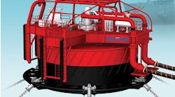
The concept design study was based on a double-drum traction winch with a storage system, spooling gear and heave compensation (suitable for all stages of deployment) installed on a representative installation vessel, the 6,500-metric tonToisa Perseus. The study considered overboarding via a davit and cantilever beams, and also floating out the payload by means of flotation tanks. Two payloads were considered, a 250-metric ton structure and a 150-metric ton suction anchor. The specification required that the lowering rope should be torque-neutral and non-jacketed, with a minimum design life of 10 years, and suitable for up to 500 deployments. A minimum rope-breaking load was also determined.
One key finding from the concept design study was that limited knowledge of rope behavior, rather than failings in winch technology, was the real impediment to development of a suitable FRDS.
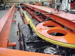
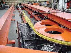
To this end, the DISH members commissioned a series of laboratory tests on fiber ropes. Three manufacturers provided rope samples for a program designed to analyze CBOS fatigue life and failure, the effect of friction on sheaves, load-elongation and axial damping properties. Pre-set specifications included an 80 mm U-section sheave groove diameter; a 2.4 m sheave diameter; a 400-metric ton minimum breaking load (MBL); and a target of 20,000 bend cycles during the CBOS tests. Rope constructions of the samples tested included eight-part plaited, 12 x 12 braided, and 12-strand braided. Materials incorporated in the samples were HMPE, an aramid co-polymer, and an HMPE/liquid crystal polyester (LCP) blend.
Rope samples were connected to the CBOS test rig in pairs, tensioned, and then cycled by moving one of the trolleys forward and backward. The two sheaves were left to rotate freely, so as to represent the idling sheaves of a flying-sheave heave compensator. The chosen cycling period represented the typical response of an installation vessel to wave swells. Throughout the tests, the rope was kept wet, and surface temperature, diameter and load-elongation at the bent part of the rope were all measured at intervals to failure.
The team concluded that a fiber rope’s CBOS fatigue life depends on a wide variety of factors, including MBL/tension, rope material, coatings and construction. With all the samples, failure was brought on by strand breakage, due largely to mechanical wear between the strands. Overheating within the rope was much less of an issue than had been expected, and the HMPE fiber ropes ran significantly cooler than the other samples, with no apparent creep rupture. However, surface temperature readings suggested that overheating and creep rupture might cause failure of certain large-diameter ropes bearing heavy payloads in ultra-deepwater.
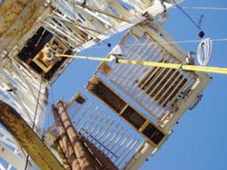
The Phase 2 program also included measurements of axial rope damping, obtained from free-decay oscillation tests. These tests involved excitation of a large mass suspended from a rope sample. The sample’s upper end was suspended from a drilling derrick that was sufficiently stiff in the vertical direction to minimize any errors that might be induced by the support structure’s motions. Measurements taken included rope tension, accelerations of both the suspended mass and the rope suspension point, the overall length of the rope sample with its termination, and the length of a section in the middle of the sample. These damping tests produced a narrow range of damping values when normalized to unit length of rope.
Other Phase 2 work included a numerical simulation study, designed to help define the dynamic motions and loads experienced by the FRDS, the lowering line and the payload in deepwater; and a computational fluid dynamics (CFD) study to provide data on hydrodynamic coefficients for a range of subsea hardware items. Among the findings were:
•Resonance increased the maximum line tension during lowering, causing snap loading or increased payload motions near touchdown in all cases and necessitating some form of heave motion suppression.
•There was good agreement between the measured and predicted values of added masses for the hardware items and also between the measured and predicted damping and drag coefficients.
•CFD proved to be effective for predicting oscillatory damping, steady-flow drag and added masses for complex subsea hardware.
Moving toward practical application
Phase 3 got underway last December, and is due to be completed in the 3Q 2006. Members continuing from previous DISH phases include oil and gas operators BP, Shell, Statoil and TOTAL, together with installation and engineering contractors Stolt Offshore, Subsea7 and Technip. Specialist supplier members from previous phases include Hydralift AmClyde, the Cortland Group (who manufacture ropes under the brand name Puget Sound), DSM Dyneema, Marlow Ropes, Noble Denton and ScanRope. New participants are lifting equipment specialists Kenz-Figee and Huisman-Itrec, together with fiber manufacturers Honeywell and Teijin Twaron. Bureau Veritas is providing Classification Society input, including advice on synthetic fiber ropes.
The main objectives in the current program include:
1. Analyzing the mechanisms of CBOS fatigue, wear and heating in large-diameter synthetic fiber ropes, based on post-mortem studies of specimens tested in Phase 2. Also, developing a mathematical model of CBOS fatigue, based on the existing test data, and calibrating this against data from previous 80-mm diameter tests.
2. Developing recognized rope life management and retirement procedures, due to the risks associated with rope failure during deployment, and the high cost of acquiring fiber ropes in long lengths. A parallel priority is to determine the procedures and personnel needed to maintain and maximize the fiber rope’s life, with associated in-situ inspection and testing methods. “The industry needs to decide when a rope has reached the end of its useful life,” BMT’s Standing adds. “One problem we identified early on is that the installation process sometimes gets held up while awaiting a suitable weather window or due to equipment failure. Ideally, you would like a rope to be able to install 500 pieces of hardware offshore before it is retired.”
3. Defining and designing a suitable FRDS for ultra deepwater deployments, one target being to develop effective heave compensation systems suitable for traction winches bearing 250-metric ton loads, and functioning in 2 m sea states.
4. Other tasks involve applying CFD further for evaluating added mass, damping and drag for a foundation unit supporting subsea modules; and numerical simulations of the lowering process of heavy and lighter payloads, such as spool pieces, partly to assess required levels of heave compensation
5. Reviewing all the work undertaken during the three phases, with the aim of generating a comprehensive description of lift system capabilities and engineering design issues. This should allow equipment suppliers, installation contractors and operators to determine whether a FRDS is feasible, and, if so, which systems and winches would be most applicable to a range of installation vessels and scenarios.
BMT has sub-contracted many of the DISH studies to specialist companies in the US and Europe. TMT Laboratories in California carried out CBOS and rope friction tests for DISH Phases 2 and 3. Subsea7 in Aberdeen undertook the Phase 2 axial rope damping tests, and Oceaneering in Aberdeen handled the conceptual design study. Oceanic in St John’s, Newfoundland, carried out hydrodynamic tests, while BMT carried out CFD and wind tunnel investigations into added mass, drag and damping coefficients at its facilities in Teddington. During Phase 3, Tension Technology International is performing post-mortem studies on the Phase 2 rope samples at its laboratory in Arbroath, Scotland, and a mathematical modelling study relating to use of larger diameter ropes.
The industry continues to push toward heavier payloads and deeper waters, and a small number of heavy lift vessels continue to stretch the deepwater installation envelope using conventional steel wire rope technology. Standing emphasized, however, that DISH is “looking for a solution that can be used on a broad range of existing offshore construction vessels, and can be achieved by relatively straightforward structural strengthening of the vessel’s deck or layout changes, for example. And whatever winching system we develop must be able to operate in a range of sea conditions, including both wind seas and swell, with a wide range of different payloads.”
As for the future, Standing says, “We are in discussions about a large-scale equipment trial, which will build on the success of DISH and bring together various development activities, including DISH, into a single focussed JIP.”•
More information about the DISH JIP may be found at www.dish-jip.com.
