Advanced analytical techniques improve prospects for VIV suppression
Dr. Victoria Sanderson, Dr. Neil Botterill, Dr. Christian Chauvet - Prospect
Vortex-induced vibration (VIV) is a prime cause of failure within many slender structures such as risers or drill pipes, and can lead to an unacceptably short asset life span.
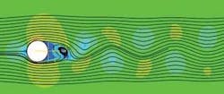
Fluid flowing past bluff objects can break into vortices that trail into the wake. This phenomenon occurs with a large range of velocities. The frequency of the vortex shedding is related to the fluid speed and to the objects’ dimensions (i.e. shape, aspect ratio).
As the frequency of vortex shedding approaches one of the structure’s natural frequencies, resonant vibrations often result, the amplitude of which depends on the damping built into the system and the motion of the fluid relative to the structure.
For stationary bluff objects, empirical relationships give the rate at which vortices are shed. These can be found using the Strouhal number (St), a dimensionless co-efficient defined as St=fD/U where f is the shedding frequency, D is the diameter of the bluff object, and U is the free stream velocity. The Strouhal number of 0.2 normally can be applied for a circular section, although it can vary with Reynolds number.
For bluff objects free to move, the shedding frequency can be predicted for most flow speeds using the same empirical relationship. The exception is when the free stream velocity reaches a point where the shedding frequency is close to the natural frequency of vibration of the bluff object. At this point resonance occurs, increasing in the amplitude of vibration to an extent where the rate of vortex shedding is controlled by the rate of oscillation. This begins the lock-in effect.
If the flow rate is increased beyond this point, the shedding frequency will persist at the natural frequency of the object. At a flow speed a few percent higher than the value where lock-in begins, the surrounding flow field disrupts the oscillations and breaks the lock-in, at which point the shedding frequency returns to the Strouhal relationship.
Subsea applications
Susceptibility of risers to VIV is a major consideration in the design phase and guidelines are available to assess the phenomenon. These are based on an empirical approach, with correlation derived from simplified systems and experience. They require considerable knowledge of the system, including local flow conditions and the structural characteristics of the riser, including its natural frequencies.
Riser construction and positioning can be more complex than guidelines can realistically represent. For example, the riser may be shielded in some way so determining the flow field is non-trivial. Interactions between the flow around a riser with surrounding objects can be the cause of VIV, which would not occur if the riser was isolated. Further, the riser may be arranged in a bundle and simple correlations developed for a single cylinder do not apply.
Numerical methods have proved mature enough to predict VIV with a reasonable degree of accuracy. Computational fluid dynamics (CFD) and finite element analysis (FEA), however, allow a far more confident assessment of the riser’s susceptibility to VIV. These provide the advantage of improving system understanding rather than generalizing to a correlation.
CFD allows the prevailing flow conditions to be ascertained while FEA can be used to ascertain the natural frequencies in the system. FEA combined with understanding of the flow field can then be applied to determine the integrity of the system through creep and fatigue analyses.
Coupled versus uncoupled
A study does not have to be costly. The complexity can be tailored to project requirements. The analytical approach can be broadly categorized into two approaches: uncoupled and coupled.
An uncoupled analysis considers the structure and the surrounding conditions separately, then compares a key aspect such as the frequencies observed in the fluid with the natural frequencies of the structure. For example, the analysis of a transient CFD simulation provides the dominant frequency in the flow around a riser. These then can be compared to the natural frequency of the system calculated by the FEA to determine whether any of the frequencies in the fluid might lock into the structural frequency, which would result in vibrations.
The uncoupled approach can be combined with guidelines, and the analysis used to build confidence in parameters required for correlations. Typically this could be estimating the local flow field in the region of the riser or the natural frequency of a structure.
A coupled analysis directly simulates the fluid structure interaction (FSI). At every time step, the force on a structure resulting from the flow field is transferred to the FEA code and the motion of the structure is calculated. Subsequently, the displacement of the structure modifies the flowfield. A constant coupling between CFD and FEA codes allows prediction with a high level of accuracy of the motion of the structure due to VIV. The coupled interaction can become critical as the motion generated in the riser by the fluid can change the vortex shedding frequency.
VIV predictions now can be incorporated easily into subsea structure design. These analyses can be used to identify area of concerns where VIV is anticipated, to recommend remedial actions, and to save costly subsea system repair operations.
Similar coupled analyses can simulate many other phenomena commonly seen in the oil and gas industry. An example is the simulation of slamming effects when a structure is dropped into the water.


