Diverless pile connector allows re-leveling during structure life
By Peter Curry
Britannia Engineering Consultancy
There is a tendency to believe that diverless problems demand sophisticated solutions. However, adding complexity introduces cost penalties and issues surrounding inspection, maintenance, repair, and reliability. For diverless structure/pile connections, the available options have been limited to swaging, remotely operated vehicle (ROV)-deployed grouting, or the alternative latch-type joint using proprietary plated piles.
These typically involve mobilizing specialist teams and/or equipment offshore for the connection operation. This operation can keep the installation vessel in the field for an extended period, and overall costs are very much weather-dependent.
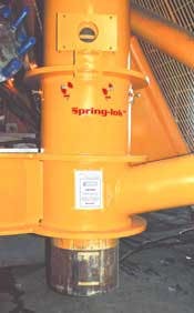
In response, Britannia Engineering Consul-tancy developed a diverless structural connector called Spring-lok, designed to actuate underwater automatically and effect an instantaneous connection. The decision to overboard and secure the facility can be safely taken within the minimum weather window, avoiding allowances for connection operation, verification, and/or equipment malfunction.
The system has been incorporated so far into two recent offshore development projects, BP's Magnus enhanced oil recovery (EOR) scheme in the North Sea and Shell's Malampaya off the Philippines. The device was targeted initially at diverless subsea piling, but should find wider application in other areas of subsea engineering. It is water depth-independent, and offers confirmation of joint engagement via a variety of visual options.
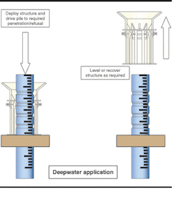
By virtue of its ratchet-like features, it provides the contractor with the ability to level the structure, and is also available as a fully releasable joint.
Joint function
The joint is self-activating and operates via interaction of the radial tension spring elements and pile groove or collar features. It avoids secondary connection operations entirely, having no moving parts other than the forced displacements. It is intended for use with conventional tubular piles and is compatible with standard piling equipment.
Spring-lok can be deployed in a wide range of configurations to suit different applications. In the case of a bi-directional joint, the connection consists of two sets of vertically mounted reciprocating leaf springs arranged on a circumference and housed within the pile sleeve as a pre-assembled can.
The springs are nested and interlocked in opposing directions. Spring bases are welded to spring support rings that double as pile centralizers, while radially segmented profiled clawed springheads are mounted at each free end. These springheads have a machined bearing surface and an external sloping face for contact with the pile tip during insertion. The pile is a conventional specification circular section with a heavy-walled pilehead section, complete with opposing grooves.
One set of springheads (either upper or lower) is fitted with a spring head retractor bolt mounted centrally on a target plate. By running the retractor bolts, both sets of linked springheads disengage from the pile grooves. Alternatively, the joint may be used in a simple (non-releasable) uni-directional format using a profiled pile collar.
Other applications
Aside from conventional piling, the system can be used for post-installation piling and for running of structures and equipment onto pre-set conductors or guideposts. The capability to remotely attach and release the joint's structures allows large subsea facilities to be constructed in a modular or sub-structural format. The connector can be used with any type of piling method (impact, vibro, or suction) on manifolds, isolation valve assemblies, wellheads and protection structures, tether terminations, and jacket templates.
Use of Spring-lok in shallow water applications will also remove the need for dangerous and time-consuming diver operations associated with drilling and pinning. A minor adaptation allows the joint to be used as a pile hang-off device for use with drilled and grouted piles for rig-based installation - freeing the draw works for the curing period.
To allow for possible overdrive, the system can be fitted with either a steel driving collar or an elastomeric collar to absorb driving energy following engagement, although this option should not be necessary if modern hydraulic impact hammers are used.
To the observer monitoring operations from the surface control vessel, there is no doubt about the joint status. The condition is clearly indicated by the eight radial target plates located equi-distantly around the full pile sleeve circumference.
The clear gap between the spring support rings will accommodate standard API pile fabrication tolerances. This gap limits the maximum possible pile inclination to less than 0.3 degrees. The small resulting misalignment of the bearing faces is allowed for in the design, in accordance with Lloyds Register of Shipping recommendations.
Should the mudline topography necessitate a structure leveling operation, the system provides a means to achieve this. The procedure would involve driving the high corners first until the device engages. A simple geometric calculation would then be carried out to determine the required reduced penetration for the remaining piles. The structure is then lifted, using either surface vessel assistance or ROV-operated local jacks, until the remaining connections engage. For shallower waters where lock-down may be an issue, use of a springer line would be recommended.
An optional polychloroprene annulus may also be provided against which the pile will seal during driving. This contingency feature may be considered for joints located very near to the mudline.
A generic design approach has been developed and approved by Lloyds Register of Shipping for the connection. The approach has been verified by finite element modeling, and a detailed testing program monitored by LRS representatives. The installation/engineering contractor is required only to provide the pilehead design forces (axial load shears and moments as applicable) along with the preferred pile diameter.
Spring-loks are available over a full range of API section sizes, with capacities from 50 metric tons to over 1,000 tons per connection, and in standard sizes from 6-in. to 42-in. diameter.
BP Magnus EOR
The range of soil conditions to be considered for this project was extreme. The main pipeline end manifold structure (PLEM) was located on the continental shelf break 200 km west of the Shetland Isles on very hard clays, up to 700 kPa with cobbles. The Magnus platform riser bridge, by contrast, was located on a variable depth, and very weak layer of drill cuttings (5 kPa) over sand to depth.
The 140-ton PLEM structure designed by JP Kenny was required to resist beam trawl interaction loads of 102 tons lateral, and trawl recovery loads of similar magnitude. Within diving depths, the installation contractor (Stolt Offshore) opted for a Spring-lok device to enable a diverless installation and piling program. Integration of the units into the main structures was carried out at the main fabrication yard by introducing the connections into the pile in the form of inserts.
Each connector was then subject to shop trials using the pile heads and witnessed. In the field, the diverless overboarding and securing of the structure to the seabed with the device was followed by an ROV-based spool metrology exercise in preparation for a later spool tie-in phase.
At the Magnus platform, the 40-meter-long multiple riser bridge structure was overboarded, driven, and connected again within hours in a simple diverless operation.
Malampaya
The installation method adopted for the Shell Malampaya PLES structures called for the assembly to be storked onto the flowline, welded out under tightly controlled conditions (due to corrosion resistant alloy lining requirements), and deployed to the mudline (850 meters depth) using the abandonment and recover winch line from Allseas' lay vessel Solitaire.
The in-line structure had to support the pipeline at the required elevation, accommodate the termination facility (valves/remote pig receiver and diverless hub), provide for remote installation and ROV operations, and accommodate a pipeline expansion of up to 2000 mm. The foundation system needed to cater for a wide range of potential soil strengths (as low as 3 kPa) plus future long term and differential settlements.
The facility inclination angle was an important additional consideration addressed within the design. The solution developed by JP Kenny was a lightweight facility set on an Inconel/Tufnol sliding track, in turn mounted on a perforated support base. Deployment was undertaken via an hydrostatically relieved, integrated rigid bridle frame pivoted about the horizontal plane. The frame was conservatively sized for deployment based on a flooded line with capacity to transfer load under a full 180
The structure needed to be low profile with a minimum projection below the mudmat to allow vessel deployment. Suction piles were not suitable and were unable to mobilize known competent soils at depth. Due to difficulties in obtaining site-specific representative soil data, there was some unease over potential long-term settlement. In the worst case, excessive settlement could restrict access or compromise the pipeline hub connection so the decision was taken to incorporate a pile connection facility as a contingency.
The performance of the structure is to be monitored and in the event that large or differential settlements develop during the operational phase, piles will be driven. Driving at depths of 1,000 meters has already been achieved using impact hammers (Menck), and depths of 3,000 meters are achievable using current technology. Application of Spring-lok on Malampaya assisted in providing a low center of gravity design, ensuring a stable deployment, and with the yoke system, subsea rotation was avoided.
In the event that structure settlement may need to be reduced or eliminated, the connector can facilitate re-leveling at any time in the future. Crucially, the design called for the ability to recover the facility should the isolation valve, pipeline hub, or pig trap develop problems during the 25 design life structure. Use of Spring-lok provided for both of these demands. The PLES facilities were installed successfully and without incident.
As Shell's Luuk Wellens explained, "their primary purpose was as a contingency measure to resolve the foundation concerns by providing a cost-effective, robust releasable pile connector that will remain as a valuable option for the full design life of the facility."
This novel "pile and forget" joint demonstrates that simple solutions to diverless or deepwater technology problems are still available. It offers a key alternative when selecting foundation type for both shallow and deepwater.


