R. Fleischmann, P.E.,
Judy Maksoud, International Editor
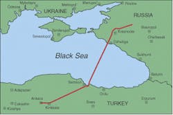
The Gazprom/Eni joint venture recently completed the second phase of the Blue Stream gas pipeline across the Black Sea from Russia to Turkey. The $2.3-billion pipeline links the Beregovaya compressor station near Dzhubga on the Russian shore to a compressor station near the city of Samsun on the Turkish shore. The pipeline will carry an estimated 16 bcm/yr of Russian gas to Turkey.
Pipe laying began in October 2001, with the first of the two parallel lines reaching the Russian coast in February of this year. Work on the second line began immediately and concluded in June. Hydrotesting and pre-commissioning were scheduled for completion by the end of September. Now, a year after initial work began, first gas delivery is scheduled to take place this month.
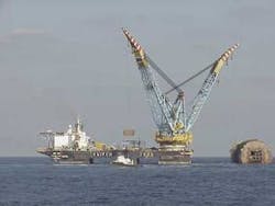
The two 24-in. pipelines that make up Blue Stream run 385 km across the Black Sea and were laid at a record water depth of 2,150 m by Eni's Saipem 7000. The Castoro-8 completed tie-in work on the Turkish side.
The Saipem 7000 was converted from a dynamically positioned semisubmersible to a J-lay vessel in 1999. The Black Sea line marked the first deepwater installation using the J-lay system. The installation set a water depth record and in its success has revolutionized pipe laying.
The J-lay system
The J-lay technique uses a vertical system that allowed the Saipem 7000 to place the pipeline at a depth greater than 2,000 m. In systems that pre-date this design, the tensioners are almost horizontal, positioning the pipe in the shape of an S from the vessel to the seafloor. The horizontal orientation is limited to several hundred meters.
The vertical J-lay system employs pipeline-holding tensioners suspended in a tower. The tensioners curve the pipe into the shape of a J as it enters the water at a nearly right angle.
The electrical system that drives the pipe-laying equipment is the critical component of the pipe lay operation. The system contains dry-type transformers, switchgear, thyristor and control cubicles, and a 24-Vdc uninterruptible power supply. The system uses dc motors and digital controls for precise positioning, a bus (LAN) network, and operator-friendly control and alarm displays. Throughout, only standard off-the-shelf industrial-type components suitable for marine application are used.
Supplying power
Power is generated at a voltage +level of 10 kV/60 Hz and is stepped down to 500 V by dry-type cast-resin rectifier transformers, designed for thyristor firing angle control around 90°.
The 500 V/5,000 amp switchgear for tensioners and winches is of almost identical design, arranged in two cubicle line-ups, each with two buses linked by a (normally open) tie breaker. Each bus is fed by a 3,750 kV amp transformer via a 5,000 amp air circuit breaker. Air circuit breakers also supply the thyristor-controlled drives, and molded case circuit breakers serve the drives' auxiliaries.
The split-bus arrangement meets the double purpose of reducing the prospective short-circuit current on the bus to a manageable level and – due to the phase-shifting properties of the transformers – reduces harmonics on the 10-kV supply system to a 12-pulse reaction.
The motorized air circuit breakers are operated from a control desk on the bridge through a programmable controller and serial bus system. A local manual emergency operation can be enabled with a key safety-switch without the programmable controller system.
Three caterpillar-type drives in the tower hold the pipeline. Four dc shunt-wound motors at 423 kw give each tensioner a rating of 175 tons at a maximum pipe laying speed of 40 m/min. The electrical tensioner drives offer power savings because active power is consumed only when pipe is laid. At standstill, current is mainly reactive, resulting in reduced fuel consumption of the diesel engines. A kVar-compensator can further reduce the reactive power consumption.
The double-drum abandonment/recovery winch is rated 550 tons at 40 m/min and can handle steel ropes up to 5 in. in diameter. Maximum abandonment/recovery speed is 80 m/min. The winch serves for the lay-down and the recovery of the pipeline on the seafloor. It operates in conjunction with a tension-controlled 370-kw spooling winch. The automatic rope-guidance mechanism of the spooling winch is also driven by a dc motor and is an integral part of the spooling winch control.
System control
All of the controls are digital, graphically programmed, multi-processor systems. Two-wire cables link all digital/analog input/output stations throughout the ship. Fiber-optic cables connect the processors of the control subsystems for the tensioners and winches. Control-cable wiring is reduced to a minimum, which not only saves installation costs, but also increases system reliability.
The system is operated and monitored from a control desk on the bridge, while control stations at the machines allow for local operation, primarily for maintenance purposes.
Author
Reiner Fleischmann (ReinFleischmann@ aol.com) is an electrical design engineer and project manager with a degree from Technical University of Berlin (West). He has extensive experience in design, system integration, testing, commissioning in transportation, marine (ship propulsion systems, power and distribution, special drives for pipe layer vessels), and hydro industries.
