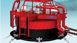
WELL TESTING Proper oil, water atomization needed for burner combustion
New burners can achieve high test flow rates without sheen
Tim Young
Halliburton Energy Services
Smoke was eliminated on the same head with a 25% water cut.
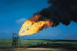
Smoke produced while flowing 6,350 b/d through a 4000 b/d head.
Operators conducting flow tests to gain vital information about their reservoirs can operate in an environmentally friendly manner by properly atomizing crude oil into fine droplets for efficient flaring. Disposal of oil, via combustion, during offshore well tests is typically viewed as a cost effective approach to gather reservoir information compared to storage and re-injection options. Previous well test burner designs were less than desirable environmentally and in many cases left a sheen on the water from unburned hydrocarbons falling out of the flame and typically exhibited dense smoke plumes.
By proper atomization of the crude oil droplets to improve ignition and combustion, operators can flare crude oil at an efficiency rate of 99.993%. The key to this efficiency is a modular burner system, which in its three head (nine atomizer) configuration can flare up to 9,000 b/d smokeless, and up to its rated capacity of 12,000 b/d without leaving a sheen on the water.
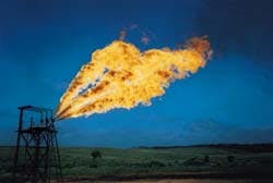
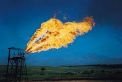
Injecting water into the oil provides smokeless operation at 9,000-12,000 b/d, also with no visually detectable fallout.
Need for flow testing
Production flow tests are a vital step in the life of a well, since the operator must be able to evaluate the long-term production potential of a well before he can make an informed decision to invest in the capital equipment and other expense required to bring the well to production. Operators foregoing full production tests, relying on other test methods as an attempt to reduce exploration expenses, run the risk of not realizing the full potential of their investment.
Soliman et al concluded that what is not detected during a drawdown cannot be detected during the buildup period. This can be easily visualized in a test where more than one flow regime may be encountered such as effect of boundaries, dual-porosity systems, fractured reservoirs, etc. For example, if the drawdown test was too short to observe the effect of a boundary, the buildup could not be used to calculate the distance to the boundary regardless of how long it might be. In support of the above conclusion, Earlougher and Kazemi stated that the radius of investigation during a drawdown test should be at least four times the distance to a sealing fault to allow observation of the doubling of the slope during a buildup test.
Another example is a buildup test performed on a dual-porosity system. In a dual-porosity system, there is a storage effect followed by the effect of the fracture system, a transition period, and eventually, the total system. Soliman's work showed that a buildup test would not reveal a flow regime that had not been investigated by the preceding drawdown. For example, if the drawdown test was terminated before the matrix system was investigated, the buildup test would not be able to reveal reliable information on that portion of the reservoir. This discussion indicates that although a short flow period followed by a long buildup period may be acceptable in the case of a homogeneous reservoir, in a majority of cases a long flow period would be necessary.
Background
With today's emphasis on environmental awareness, the industry requires operational procedures and equipment that are both competitively priced and protect the environment. Burner designs in the past operated at less than desirable efficiencies and resulted in unnecessary pollution creating the need for a new design. The difficulty of this combustion application is due to the fact that it occurs in open air with the large flow rates and a variety of crude oil compositions.
To create a new burner, the processes by which these pollutants were created were analyzed along with previous solutions for oil combustion. As a result of these studies, a highly efficient well test burner (WTB) combusting 99.993% of crude oil was developed. Using the same basic operating principles as its predecessors, the current WTB emerged as a modification of existing practices using highly efficient atomizers to improve combustion performance.
Combustion process
Most oilfield burners are similar in design, consisting of various atomizers and an ignition source. Either oil pressure, air, or a combination of both provide the energy to atomize the fuel. The atomized liquid fuel spray is then ignited by a pilot flame. Liquid fuel spray combustion is actually the burning of hydrocarbon vapors around these droplets. Droplet vaporization is a function of the initial droplet size, fluid properties, and the heat of combustion.
Achieving proper combustion in an open-flame burner is very difficult due to unknown or constantly changing variables such as flow rate, flow pressure, hydrocarbon characteristics, and environmental conditions. Dense smoke clouds and unburned oil fallout may be significantly reduced or eliminated during well test operations by using improved burner technology.
The current WTB incorporates several new design and operational features which significantly reduce smoke and hydrocarbon fallout. One such feature involves atomization, the production of small hydrocarbon droplets, that vaporize quickly to eliminate raw oil fallout of the flame. High burner-nozzle exit velocity to improve atomization, and the use of multiple tips which discharge in a unique array improve flame turbulence and air ingestion to effectively eliminate smoke and fallout over a wide range of oil flow rates.
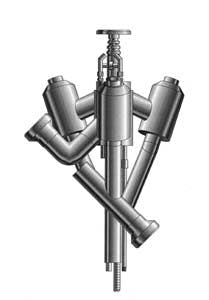
Well test burner nozzle formation
Burner nozzle formation
Tests were conducted on burner atomizers to determine which would most effectively eliminate smoke and fallout. These tests included burns using over 20 variations of pressure swirl, adjustable orifice, prefilming, and internal-air mix type atomizers. The objective was to select the atomizer type that most efficiently provided adequate atomization over a wide range of flow rates and oil types.
Testing of the current WTB involved a variety of flow rates up to 12,600 b/d with water content varying from 0% to 35%. In addition, both heavy and light oils were included in the testing. Internal air mix type atomizers were the best performers and remaining testing centered around this design.
The final engineering test phase included eight separate tests. The purpose of the first four tests was to gather information at an initial rate of 3,145 b/d per head. Each head has a nominal rating of 4,000 b/d and the objective was to evaluate the effects of multiple heads. Further testing involved various flow rates, oil gravity, and water contents. For example, Test 5 was a 12,000 b/d maximum oil-rate test operating three heads, while Test 6 involved the maximum fluid rate with a 15% water cut.
In Test 7, a fixed-fluid rate test, injected water into the oil at 15%, 20%, 25%, and 35% of the total flow rate of 6,350 b/d through one head, exceeding the nominal rate of 4,000 b/d. These tests demonstrated the excessive smoke associated with high rates per head and revealed that by injecting water upstream of the pump, it was possible to completely eliminate the smoke without affecting fallout.
Test 8 demonstrated the burner's capability to efficiently combust an 18° API heavy crude oil. Tests 1-7 lasted 15 minutes and required an air flow rate of 1,500 scf/m per head (100 psi), with an oil pressure of 200 psi at rated flow.
Final results were validated by a Norwegian environmental testing company who concluded the following:
- The current WTB efficiency, based on fallout volume, was far less than any previous design tested and well below the limits of the Norwegian authorities.
- Injecting water at rates of up to 35% of the total flow rate provided stable combustion conditions without a negative impact on burner performance.
- Startup and shutdown periods for the flare exhibited were exceptionally clean.
Operation
The current WTB uses a pilot system with remote ignition that includes an extremely stable pilot and gas jets directed to each nozzle. This arrangement quickly initiates oil spray ignition during startup and provides a stable ignition source during shutdown. Pilots are typically fueled with propane or separator gas, however, diesel pilots are also used. The basic operating sequence for the burner is as follows:
- The pilot portion of the ignition assembly is lighted either locally or by an electrical switch.
- Gas is flowed through jets on the pilot assembly to ensure there are distinct gas flames directed toward each atomizer.
- Gas supply is then shut off and the burner is left in standby mode. Because the pilot portion of the ignition system is exceptionally stable and uses an independent propane supply, it is ready whenever the operator wishes to flow. Gas jets are usually started up with propane and later switched to separator gas. Using more gas than the pilot portion, these jets are plumbed for the dual source.
- Compressed air is supplied at a pressure around 100 psi. Because the air supply is an integral ingredient to proper performance, lines must be properly sized and an adequate source made available for the number of heads expected to be operated.
- Before oil is supplied to the burner, gas jets are turned on. Immediate ignition occurs as the oil is discharged from the burner atomizers. Flames are typically independent at low rates and merge into one at higher rates.
- Shutdown is accomplished by ceasing oil flow and turning off gas jets and pilots. No adjustments should be necessary during operation.
Based on previous testing and experience, smokeless operation can be expected up to about 3,000 b/d per head. Higher rates up to 4,000 b/d may create a rapidly dissipating smoke plume. If water is supplied to the oil, the burner provides smokeless performance up to and exceeding the maximum rating.
Injecting water externally into the flame is not advised. For best results, a water curtain should be placed in a vertical plane 15-20 ft perpendicular to the boom to reduce thermal radiation and smoke. To help ensure proper functioning, compressors, pilot gas supplies, and water cut percentages should be monitored during operation.
Conclusions
Current WTB technology provides a highly effective disposal system for both land and water-based operations. Various tests of up to 12,580 b/d have proven the burner to be 99.993% efficient, eliminating smoke and fallout over a wide range of oil-flow rates. Operators requiring reservoir information from well tests may collect it in a cost effective, environmentally responsible manner complying with strict environmental regulations. Proper crude oil atomization through multiple nozzles in a unique array provides the operator with an environment-friendly solution to well test disposal needs.
REFERENCES
Soliman, M.Y., Hunt, J.L., Rezk, M., and Puthigai, S.: Considerations in Modern Analysis of Well Test Data," SPE 36123, Fourth Latin American and Caribbean Petroleum Engineering Conference, Port-of-Spain, Trinidad & Tobago, April 1996.
Earlougher, R.C. and Kazemi, H.: "Practicalities of Detecting Faults From Buildup Testing," JPT (January 1980).
Copyright 1996 Offshore. All Rights Reserved.
