Part II: Matching drilling tubulars to needs and avoiding overload
Purpose-qualified drilling tubulars
PART II: This is Part II of a three-part series on purpose-qualified drilling tubulars, their grading and testing. Part III will appear in a subsequent issue.
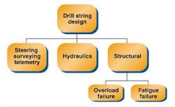
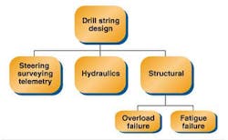
An engineer about to design a drillstring will have three main areas of concern: steering, surveying, and telemetry; hydraulics; drill string structural soundness. It is only the structural aspect of the drillstring design that will be addressed in this article. In working the structural problem, the engineer will:
- Predict the loads the drillstring will need to carry
- Configure a drillstring with metallurgical and dimensional attributes adequate to carry the predicted loads, with a safety factor to handle uncertainty.
- Ensure that the (used) pipe picked up from a contractor or rental company meets the minimum attributes needed (the engineer gets the pipe "inspected," telling the inspector the minimum criteria to use for accepting material).
Part I of this series (September) demonstrated how market forces caused the industry to standardize on a single set of arbitrary acceptance criteria for used drill pipe - Premium Class. This creates inefficiency in two ways:
- Many of today's wells push the limits of drillstring structural capacity. Using an arbitrary 25-year-old standard for acceptance during inspection can increase the risk of drillstring failure on critical wells.
- On the other end of the scale, drilling equipment is needlessly changed out, and even retired, when it wears beyond the arbitrary Premium Class standard. This makes for poor economics when, from an engineering standpoint, the equipment may serve perfectly well in noncritical mainstream drilling applications.
With analytical tools that are widely available today, we can easily forecast drill string loads and load capacities. A 'purpose qualified' approach to accepting drilling equipment means moving toward matching the capacity of the equipment to the loads we expect to apply. We will divide our discussion into two sections. Designing a drillstring to prevent overload failure is the topic for this installment, and designing to prevent fatigue failure is the topic for Part III.
Overload failure
Overload failure occurs when the load applied to some component of the string exceeds the load capacity of that component:
(Eq. 1) LA/LC > 1.0
Where:
LA = load applied to a component in the string
LC = load capacity of that component
The principle loads we apply at the surface are tension and torsion. These result from supporting the weight of the drillstring, and from hole drag (resistance to drillstring movement). Both of these applied loads - hanging weight and string drag - decrease in magnitude as our point of interest moves down the string. Also, as our point of interest moves downward, load capacity of the string will change each time we encounter a change in component type, size, grade or class.
Since less drill pipe strength is required the lower we go, drillstrings usually have less load capacity as we move downward toward the bottomhole assembly. Therefore, overload failures will happen near the surface (where loads are highest) or at some drillstring section top (where load capacity ordinarily takes a sudden move downward). All this may seem complex, but preventing overload failure is simple with today's computer tools and inspection capabilities. This assumes, of course, that we apply good engineering and reasonable care in our planning, inspection, and drilling operations.
Load factor
The easiest way to visualize the overload state anywhere in the string is to think in terms of 'load factor.' Load factor is the percent of capacity being used on a component, taking our design safety factors into account:
(Eq. 2) LF = (DF) [LA/LC]
Where:
LF = load factor (percent of load capacity being used)
DF = design (safety) factor (DF> 1.0)
LA = load applied to a component in the string
LC = load capacity of that component
The operating range for load factor will be from zero (no load applied) to 1.0 (overload imminent). Since loads and load capacities will vary widely over any drill string, load factor is everywhere variable. A load factor less than one at a point of interest indicates that conditions at that point are inside our allowable design window, and vice versa.
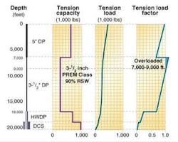
Consider an example (accompanying figure), which shows the tension state of a 20,000-ft drillstring hanging in a vertical hole. The drill string is constructed in four sections: Premium Class 5-in. drill pipe, Premium Class 3-1/2 in. drill pipe, heavy wall drill pipe (HWDP), and drill collars. The four different sections have different metallurgical properties and dimensions, as well as different connections, so the tensile capacity of each section is different from all the others. Every component must carry the buoyed weight of all components below it, so the tension load decreases continuously as we move downward.
Now apply equation (2) at all points in the string. The resultant is load factor, which is plotted on the third graph (accompanying figure). Here, we see immediately that the 3-1/2 in. drill pipe is overloaded from about 7000 ft to 9000 ft. To fix this problem, our first instinct might be to replace 2000 ft of 3-1/2 in. pipe with 5-in. pipe. While this would correct the problem at the 3-1/2 in. section top, the added weight would overload the pipe at the surface. Other options might be to use different, stronger components either at the surface or the 3-1/2 in. section top. Depending on the remoteness of the operation and the availability of alternative material, such options can get quite expensive.
Alternative
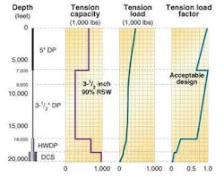
However, a simpler and probably less expensive solution may be available. We know that it's very unlikely that all of the 3-1/2 in. pipe in inventory is worn to the limit allowed by Premium Class - 80% remaining body wall (RBW). Let us assume that, instead, enough 3-1/2 in. pipe with at least 90% RBW can be found in inventory to fill our order. If so, we could make the present design acceptable by inspecting the pipe to 90% RBW.
We will instruct the inspector to alter his acceptable limit on tube wall thickness to 90% RBW, keeping all other attributes required for Premium Class. If enough stronger pipe is there, we have achieved an acceptable design by increasing the load capacity of the weak section. In practice, the same amount of the same pipe will probably be used, and the engineer has fixed his design overload problem at zero cost (accompanying figure). Of course, if the inspector cannot find enough stronger pipe in available stock, other pipe will have to be located.
Today, we often encounter the need to adjust acceptance criteria away from traditional Premium Class values. In remote operations, for logistical or political reasons, replacement equipment is often simply not available. In these situations, the alternative to using what's in hand can be very expensive. And too, if sound engineering analysis shows that the available "substandard" equipment is perfectly up to the job in hand, why not use it?
Examples
A recent example occurred on a deep vertical hole in Colombia. The 6-5/8 in. drill pipe tool joint was worn well below Premium Class, but the pipe otherwise met Premium Class requirements. Faced with a rig shutdown and very high transportation costs to change out the pipe, the operator performed a load analysis. Expected torsional loads turned out to be low, yielding a load factor, even with the significant wear, of less than 0.2 (20% of capacity).
Thus, the arbitrary Premium Class requirement being imposed by the operator represented an egregious over-design for the application. The operator relaxed his requirement, accepted the pipe in its worn condition, and safely and economically finished the well.
On the other end of the spectrum, deepwater drilling imposes extraordinary tensile loads on running and landing strings. In deepwater drilling, designers now increase drill pipe inspection acceptance criteria above Premium Class, and set other special requirements, to accommodate these higher loads. Although this practice is increasing, it is still not common. So, as you plan to change an inspector's normal routine, make sure you take pains to communicate your needs exactly and repeatedly.
Drillstring politics
Even political considerations are affecting drillstring designs. In some countries without a well-established drilling infrastructure, it can be very difficult to move drilling equipment across national and even local borders. We could speculate (charitably) that this difficulty arises from bureaucracy, or (less charitably) that it is driven by the personal economic needs of the involved bureaucrats.
Whatever the cause, contractors and project lead companies are well aware that the equipment they move into these locales may, only with extreme difficulty, be retrieved. Understandably, these companies are loath to place large amounts of their best equipment at risk. However, the resulting lack of locally available, good quality replacement equipment greatly increases the odds that the operator will be forced into 'lose-lose' design decisions.
The following true story illustrates this problem: An email was received from an operator who was drilling in one of these areas. Attached were photographs of three stabilizers, all of which had large circumferential body cracks. The operator queried thusly: "Which of these stabilizers is best to run in my hole?"
When we replied that none of them were satisfactory, the operator immediately shot back: "These are the only three of this size in-country. We're going to run one of them. Which one is best?"
Before letting contract
Do your engineering before letting your contract. One of the biggest impediments we encounter in these areas is the language in existing contracts. If you're negotiating a service contract for a locale that has a weak drilling infrastructure, don't rely on old contractual "boilerplate" that may have got you by in better-developed infrastructures. High-sounding but meaningless references to "API Inspection" or arbitrary benchmarks like "Premium Class" will probably not get you what you need. Instead, before letting the contract, make sure of the following:
- Do preliminary design and load analysis on typical wells in your project.
- Determine the minimum drill string attributes you'll need, and make these attributes part of the service contract.
- Take steps to measure and verify that these attributes exist on the equipment, before it's shipped into the country.
In the third and final installment (Part III), we will look at "purpose qualified" drilling equipment from the standpoint of drillstring fatigue.
