PRODUCTION TECHNOLOGY: Compact in-line separation solves severe slugging problems on Statfjord B
The CDS/Statoil Degasser is an in-line device that separates gas and liquids more compactly than existing separator designs. It has no moving parts and requires no power. Due to a very simple but effective control system, the unit reaches very high separation efficiency regardless of flow fluctuations. The separation efficiency is above 99.5% gas from liquid, while the separated gas is 100% free of liquid.
The requirement for an in-line degasser came from operational problems encountered on Statoil's Statfjord B platform, located in the North Sea. On this platform, the water streams from the main separators are fed to a bank of hydrocyclones in order to reduce the oil in water prior to overboard disposal. After the hydrocyclones, the water flows through a level control valve with a pressure drop of about 60 bars that subsequently causes a lot of gas to come out of solution.
The resulting two-phase flow then flows to a degassing tank situated approximately 20 meters above, where the gas goes to the flare, and the water is sent for overboard disposal. As water production increased over the years, the gas in the line between the level control valve and the degassing tank created more and more problems due to the slug flow regime. This caused vibrations in the pipeline to the degassing tank and in the tank itself that were sufficiently strong to limit production.
To end these vibrations, the only option was to take out the gas immediately after the control valve. However, a rough sizing of a conventional degassing tank required a vessel about 10 meters long with a diameter of 4 meters, for which there was no plot space available.
The preferred location for the new degasser was in place of an existing 18-in., 8.5-meter-long horizontal spool piece, located downstream of the level control valve prior to the flow rising vertically to the degassing tank. It was due to this that the concept of an in-line centrifugal degasser was born. Statoil and CDS Engineering entered a partnership in order to develop this technology, which consisted of experimental and theoretical work.
Experimental work
At the outset of the project in 1998, it was intended to use computational fluid dynamics (CFD) to assist in the initial design. However, due to the complexities of solving for a two-phase rotating flow with the CFD software available at the time, it was decided instead just to go ahead with experiments of a 6-in. model. This 6-in. test rig was designed for a water flow of 100 cu meters/h (15,096 b/d) and a gas rate of 100 cu meters/h (0.085 MMcf/d) at a pressure of 1 barg.
In this test loop, several tests were performed to optimize the design and layout of the internals to achieve the best degree of separation. This set-up was also used to develop the simple but highly efficient control system that gives the degasser the flexibility to get the perfect separation even under varying inlet conditions.
The principle of operation is that the gas and liquid flow is spun by a stationary swirl element in the horizontal section. Due to this rotation, the liquid is forced to the outside of the pipe, while the gas is contained in a central core. The liquid flows straight through to the connecting outlet piping through a reverse swirl element, while the gas core is removed from the center via an internal pipe. This gas, along with some entrained liquid, flows into the vertical scrubber part.
The entrainment of liquid is necessary in order to be able to control the unit. In brief, a pressure control valve located on the gas outlet of the vertical scrubber section controls the size of the gas core inside of the degasser by reference to the liquid level in the scrubber. If the gas core is too large, insufficient liquid reaches the scrubber, and the level in the scrubber drops. In this case, the pressure valve opens, reducing the diameter of the gas core allowing more liquid to pass to the scrubber.
Inversely, when the level in the scrubber rises, the pressure valve closes, thus causing the gas core to increase in diameter. This reduces the amount of entrained liquid flowing to the scrubber. Dry gas leaves the vertical scrubber section while the separated water flows back to the main pipe.
As can be seen, there is a minimum liquid flow required for good separation. During all tests, the gas that was separated was 100% free of liquid, which is beneficial for further downstream processing of the gas. The gas removal efficiency of the degasser was above 45 cu meters/h of water, more than 98%. The control system appeared to work very well with the degasser reacting very quickly, within a few seconds, to dynamic transients caused by changes in rate and GWR (gas-water ratio).
Of note is that the limits of the operating envelope were caused by the limits of the test loop. The pump could not give more than 100 cu meters/h water, and the gas outlet valve was completely open at 100 cu meters/h, while the degasser itself was clearly not at its limits. From these results, initial sizing rules were drawn up that could be used for the sizing of further units. In order to check these rules, it was decided to build an 11-in. test unit, after which the actual 18-in. degasser for Statfjord would be built.
11-in./18-in. units
The 11-in. test rig was designed for a water flow of 600 cu meters/h (90,576 b/d), and a gas rate of 1000 cu meters/h (0.85 MMcf/d) at a pressure of 1-7 barg. The variable pressure was used to mimic the actual operating conditions that would be present on Statfjord B. Several tests were performed to check the operating envelope and to test the control system under different steady state and transient conditions.
From these tests, it was concluded that the degasser worked almost perfectly and that it was not dependent on the system pressure. The control system worked very well. Fluctuations in gas and liquid flow and in pressure did not adversely affect the separation performance.
Again, the liquid pump and the gas compressor, instead of the degasser, determined the limits of the operating envelope. From these results, it was concluded that the developed rules for sizing and scaling of the degasser were sufficient to design the 18-in. test unit.
A prerequisite of Statoil was that before the first degasser was installed on the Statfjord B platform, a full-scale test had to be done. The purposes of these tests were to again check scaling rules and verify that if, for whatever reason, the degasser did not function, platform production would not be reduced.
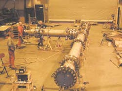
Due to the high flow rates required for the 18-in. test, a test setup was constructed at Kværner Eureka in Tranby, Norway. The 18-in. test rig was designed for a water flow of 60,000 cu meters/d and a gas rate of 100,000 cu meters/d, at a pressure of 7 barg (accompanying figure shows the actual 18-in. degasser test unit; in reality, the scrubber on the left hand side is orientated vertically both in the test loop and offshore).
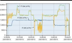
Again, as seen in the accompanying figure, the results of these tests were very good for the separation, but there were some problems with the test setup and with the controllability. As can be seen in these results, the separation of the air is almost 100%, even under changing conditions. Also, although it cannot be seen from the results, the air coming from the scrubber was free of liquid.
However, there were unfortunately two main problems during these tests that could not be solved, due to the tight time frame of the tests:
- The liquid pump could not provide a higher flow than 1,500 cu meters/h due to vibration and pressure drop reasons. Therefore, a test with the degasser under maximal flow conditions could not be performed.
- The liquid drain from the scrubber part of the degasser back into the main line was problem-free for the 6 in. and 11 in. tests, but in the 18-in. tests, the pressure at the top of the scrubber was not high enough to drain the liquid back into the main pipe.
Too high a pressure drop over the swirl elements apparently caused the second problem as well as contributing to the first problem. In order to overcome these problems, the swirl element is currently being optimized to reduce the pressure drop. This is being done with the aid of computational fluid dynamics that has improved significantly since the start of the project in 1998.
CFD calculations
CFD is a powerful tool to solve the Navier-Stokes flow equations inside all types of equipment. This tool allows for the optimization of the functionality and performance of flow related equipment. For the case of the degasser, this means the minimization of pressure drop over the swirl element for a given velocity field.
From the three tests, it can be concluded that the CDS/Statoil in-line degasser is working very well. The separation efficiency is above expectations: above 99% gas from liquid and the separated gas is 100% free of liquid. The system is stable and able to react quickly to changes in liquid and gas flows.
Before the end of this year, tests will be repeated with the 18-in. units, with an optimized swirl geometry. After this, the unit will be shipped offshore to Statfjord B for installation at the next possible opportunity.
After completion of this project, it is planned to perform tests with oil/water and gas mixtures along with higher gas fractions. The goal of the tests is to use the degasser to reduce the gas fraction of an incoming stream without generating unseparable emulsions.
In terms of platform debottlenecking, the unit can be used to reduce or eliminate existing separation equipment. Since it can be classified as a piping item, full pressure vessel regulations do not have to be adhered to.
