Autonomous vehicle offers greater flexibility for deepwater inspections
James Jamieson - Subsea 7
Dr. Ioseba Tena - SeeByte
As offshore oil and gas exploration and production has evolved, more and more infrastructure of increasing complexity in deeper water and of increased criticality to successful operations is being installed on the seabed. Installation, support, and maintenance of this equipment currently are performed by vessel-based ROVs and/or diving operations.
Subsea 7 and SeeByte are working collaboratively to provide this type of service using a hover-capable inspection autonomous underwater vehicle (AUV) operating directly from a host facility. This approach provides advantages as routine or unplanned inspections can be conducted easily and frequently without the need for a dedicated in-field support vessel.
The starting point for Subsea 7’s involvement in AUV technology was a 10-year license agreement with Southampton Oceanographic Centre (SOC), commencing in 2002, for total access to current Autosub technology. Subsea 7 engineers used the Autosub template to develop a significantly modified vehicle,Geosub, designed and licensed to operate in demanding environments in minimum 30-hour missions in water depths to 3,000 m (9,842 ft).
From that initial development phase, Geosub has been used to help develop intelligent payload systems such as SeeByte’s Autotracker, which is designed to analyze side-scan and multi-beam data in real time in order to detect and track pipelines. Output from the tracker is fused with the legacy data and is used to plan an optimal pipe survey route for the AUV.
SeeByte also applied Subsea 7 engineering in its development of the SpiNav payload system for AUV riser inspection. Through these programs it became evident that the technology was ready for transition to a hover-capable AUV performing inspection and ultimately light intervention work.
To get to the point where a hover-capable AUV factors routinely in a life-of-field project, the two companies devised a three-phase plan to de-risk the technologies, to develop operating methods, and to qualify the technology for actual use offshore. To achieve this, a Prototype Autonomous Inspection Vehicle (PAIV) is being developed as a test-bed vehicle. This has been assembled in its basic form and already has undergone an initial set of in-water tests.
The PAIV is based on a converted inspection-class ROV and does not have the hydrodynamic form that might be expected for a self-powered vehicle. It is a prototype and as such its primary function is to provide a stable and robust platform to carry the smart sensors and systems required by the SeeByte software during the development’s de-risking phase.
The vehicle that eventually deploys will incorporate all the smart technology from the PAIV and have a form tailored to the project-specific seabed infrastructure. Outwardly, it may appear unsophisticated, but it incorporates some of the most sophisticated autonomous vehicle intelligence currently under development.
System features
The initial design concept of a vehicle that can be deployed easily to perform trials in test tanks, inshore areas, and offshore sites has been achieved. Although the vehicle is small, a legacy from the donor ROV is that most of the components are rated to 2,000 m (6,562 ft) water depth, with all the components easily upgraded when required.
Key dimensions and weights of the final test vehicle, including the core vehicle and the battery skid, are as follows:
- Length: 990 mm (3 1⁄4 ft)
- Width: 750 mm (2 ½ ft)
- Height: 955 mm (3 ft)
- Weight (in air): 330 kg (728 lb)
- Depth rating: 1,000 m (3,281 ft) with option to upgrade to 2,000 m (6,562 ft)
Propulsion system. The vehicle is propelled by six proportionally controlled DC electric thrusters, each with industry-standard, high reliability brushless DC motors:
- Thruster configuration: Four vectored axial, two vertical
- Forward thrust (vectored): 36 kgf
- Vertical thrust: 24 kgf
- Lateral thrust (vectored): 36 kgf
- Maximum vehicle speed: 1.8 knots (forwards), 1.3 knots (vertical)
- Maximum hovering current: 1.6 knots (horizontal current)
Battery system. An under-slung skid can accommodate up to 12 kWh of batteries for offshore use, with a typical endurance of 7.5-29 hours, dependent on conditions, and a charge time of 2.5 hours. Pressure-tolerant lithium ion batteries have been chosen as these units are now commercially available. Currently, a simple test battery is fitted to the PAIV to provide sufficient endurance for tank testing.
Video system, lighting. A color camera (autofocus, autoiris, fixed focal length) is controlled by vehicle software and images are recorded in a digital format specific to the control system. Lighting is provided by high-efficiency lights with a power budget of 150 W.
Sensors. These supply the control system with enough information to navigate accurately and successfully:
- Doppler Velocity Log (DVL) providing an XYZ speed across the seabed
- Acoustic positioning sensor to take advantage of any existing seabed navigation infrastructure
- Digital compass, single-axis laser gyroscope
- Depth sensor (2, 000 m ±0.01% FS)
- 2D, 3D sonar systems
- GPS receiver for coarse surface alignment.
Communications. The vehicle already interfaces with an acoustic communications system and a high data rate WiFi surface system. The final communications system will include:
- WiFi transceiver for high data rate surface communications over short ranges
- Iridium satellite transceiver for long range (global) communications with a vehicle on the surface. In case the rendezvous plan is altered, this system will act as part of the emergency tracking system
- Acoustic modem transceiver; for underwater communications and positioning
- On-deck USB 2 cable link.
Emergency systems. To date, testing of the vehicle has been restricted to tanks and there has been little need for an emergency recovery system. The next phase takes the vehicle into open water and some or all of the emergency recovery systems listed below will be fitted.
- Iridium satellite transceiver
- Drop weight
- Emergency Xenon strobe light.
Modular architecture
The PAIV control system uses modular software architecture. The modules interact with an Abstract Layer Interface to ensure ease of use and compatibility when prototyping. The design allows for real modules to be replaced by simulation modules to ensure that de-risking and testing can be performed in a controlled manner.
At the center of the PAIV is the SeeTrack DP Core, comprising four modules. The Navigation module is responsible for fusing the sensor information and providing a real-time optimal estimate of the position, velocity and orientation vectors. The Autopos module is responsible for guiding the vehicle. It can interpret waypoint requests and, by using the output from the Navigation module as a reference, place demands on the different thrusters to meet those requests. The World Model keeps a representation of the world. The Mission Executive module interprets the mission, goals and assigns new waypoints to the AutoPos module.
The PAIV will be used as a de-risking platform for new modules and capabilities, for example 3D tracking of structures and navigating in the mid-water column without Doppler lock. These capabilities can be easily interfaced as new payload modules or adapted to replace existing core modules.
When deployed into a field development, there are some basic tasks that the hover-capable AUV will have to carry out during every mission and some that will be mission specific. Unlike the seabed survey AUV which is tasked to find out what is on the seabed, the hover-capable AUV will be deployed into a field development where the seabed infrastructure is relatively well understood.
Launch and recovery. The vehicle is deployed using a deck winch or vessel crane. The launch and recovery solution is both simple and robust, and taps into the techniques developed during many years of ROV operations.
Navigation. Once the vehicle is on the seabed, as part of the launch and recovery method, it will have a position error limited to a few tens of meters. This accuracy is sufficient to seed the initial frame of reference for the vehicle to start navigating. As it moves off to the start point of its first task, it takes real-time data from the vehicle sensors to identify known features and uses this to refine its position estimate.
The intelligence in the onboard software to achieve this navigation is advanced and differs from the prescriptive, script-based navigation of survey AUVs which have no real “knowledge” of the outside world, except that provided by absolute coordinate sensors, such as GPS or acoustic sensors. Survey AUVs therefore must dead reckon using way points achieved by precisely measuring distance, heading and speed, and they must fix their navigation using depth sensors and the aforementioned acoustic or GPS updates.
Inspection. As the vehicle nears the start point of the first task, the position estimate and sensor data interpolation reaches a confidence level that positively identifies the start point of the task. When this occurs, the vehicle navigates relative to the structure using the sensor data as a relative position input to the control system.
For riser inspection, the riser will be tracked by the vehicle in three dimensions. For flexible-riser inspection this active tracking is very important as any movement of the riser caused by environmental conditions will be taken into account as the vehicle maintains the optimum inspection position.
As the AUV moves along the riser image, condition information is gathered and stored digitally onboard the vehicle. This combination of sensor-enhanced navigation, positive identification of the task start point, and relative sensor based positioning of the vehicle while on-task, provides a very accurate navigation system. A high level of accuracy is achieved using relatively simple sensors that require neither the complexity nor investment seen with the seabed survey AUVs.
Intervention. The development path of hover-capable AUVs likely follows the same path that ROV evolution has followed, from observation tasks to simple manipulation followed by intervention (look, touch, act). With the AUV positioned relative to a structure, its sensor package will be used to positively identify the intervention point and initiate the maneuver.
Development of docking techniques is already well advanced. However, the tooling required for intervention will have to be tailored to operate from an AUV.
Communications. When the vehicle is subsurface, communications systems are limited to acoustic or short-range electromagnetic modems. The acoustic systems generally will be used for long-range communications in support of specific tasks. It might well be that some operations require the vehicle to report a finding or change of state.
One such operation could be the detection of hydrocarbons during an observation task, or the change of state of a valve indicator. For this type of communication the amount of data sent has to be minimized to ensure robust communications.
Operational aims
Subsea 7 and SeeByte have formulated a three-phase plan to de-risk the technologies required to provide the services needed to support life-of-field operations. These are:
Prototype vehicle development, which includes building the vehicle, developing the control software, and testing to provide a stable vehicle platform capable of operating in test tanks, inshore, and offshore locations.
De-risk applications, covering development, in-water testing, and qualification of the operational systems.
Detailed project application qualification. This phase concentrates on tailoring the technology to provide a specific service to a defined field development. This could involve producing a vehicle designed to match the requirements of the work area, using all proven and qualified software models and operational procedures.
The PAIV was built to test the initial software modules in a series of experiments performed in a water tank. These tests also serve to demonstrate the systems’ capability. To date the PAIV vehicle software has integrated the 3D sonar tracking payload module and an enhanced mid-water navigation module.
The 3D sonar tracking module can be used to build a 3D picture of the environment by detecting and tracking targets in sonar data. The PAIV can then hover and maneuver relative to these 3D structures. This technology can be applied to complex inspection procedures such as orbiting around a riser or a rectangular inspection of a ship hull or seabed structure.
The mid-water navigation module has been developed to ensure that the system can operate in the mid-water column when the Doppler velocity log must track the sea currents as it can offer no bottom-lock. The mid-water navigation module fuses the navigation data observations from other sensors in order to estimate the direction and strength of the water current.
This information can be used to provide a better estimate of velocity with respect to the sea bottom. The aim is for the AUV to be able to transit from surface to seabed and from seabed to surface as well as transiting from one target to another in mid-water while maintaining an accurate world reference. These modules have been tested in simulation and in water tank tests.
The program has also been able to interface the existing PAIV modules to a “synthetic environment” that can be used to test each module in laboratory conditions. Tests were carried out for the 3D sonar tracking module using this environment. These tests confirmed that the system was ready for deployment.
With the support of BP and Chevron, the initial phase of this development has been completed, culminating in a water tank demonstration at Subsea 7’s test tank facility in Aberdeen. The vehicle was sent on a single autonomous mission to perform a series of defined tasks.
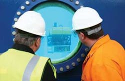
In the first part of the demonstration the PAIV moved to a position in front of the tank viewing portholes, and conducted some basic maneuvers to show off the precision and stability in the vehicle control. Next, the PAIV moved to a start point of the hull inspection task. Location data from the forward-looking sonar was used to positively identify the tank wall and lock on.
The PAIV then tracked the wall in a grid pattern to ensure 100% coverage, gathering image data as it went. A feature of this survey is the ability of the tracking algorithm to use image and position data to ensure 100% coverage of the area. This data then can be used to create a single image mosaic of the hull – a valuable tool if the real-time video data is unsteady due to environmental conditions, as a clear representation of the hull can still be achieved.
On completion of the hull inspection, the vehicle moved to a point opposite the test tank cameras to demonstrate an observation task. PAIV maintained its position in three dimensions while recording image information for some time before moving away to another inspection site for several minutes, and then returning to the first observation point. This demonstration was designed to show the system can carry out routine observation tasks that would usually require an ROV system to be on site for long periods, such as valve cycling and checking for control fluid leaks.
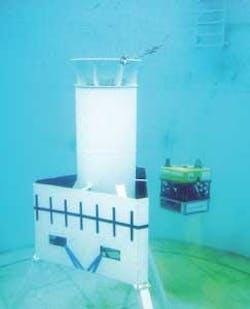
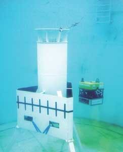
The vehicle’s next task was to survey a 5-m (16.4-ft) high structure previously installed in the test tank. The structure consisted of a vertical cylindrical section mounted on a tripod. A flat side section fitted at the lower end of the cylinder provided an additional three surfaces to inspect.
The PAIV moved to the start point offset from the upper cylinder of the structure. When in location, data from the forward-looking sonar positively identifies the cylinder and locks on. The PAIV then conducted a 360º circular clockwise inspection of the cylinder, keeping the latter in the field of view of the onboard video camera by continually adjusting the vehicle heading.
On completion of the circular section inspection, the vehicle dropped down a couple of meters to the flat sections and inspected these by moving around the structure in an anti-clockwise direction. During this procedure, tracking kept the vehicle parallel with the flat face until it reached the corner, at which point it moved around the 120º corner, changing its heading as it went to continue the inspection on the next flat face.
When the PAIV had completed the survey, it descended a couple of meters and transited under the structure. This demonstrated the flexibility of an autonomous vehicle with no tether when accessing difficult-to-reach areas. On completion of this task the vehicle transited back under the structure and surfaced to upload gathered data via the high speed WiFi link.
This is an edited version of a paper delivered at the DOT International conference at New Orleans in January 2009.
