Mittelplate field protected
by sensitive equipment
by sensitive equipment
Ulrich Frank, Heinz Berners
RWE-DEAWerner Sickinger
WintershallAnthony Hadow
BaroidKen Sudron
IPM SchlumbergerGovert Klop
Deutag
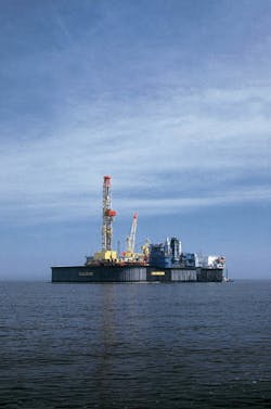
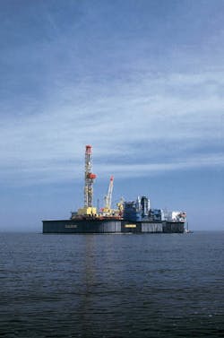
The artificial production and drilling "island."Over the past decade, 10% of the recoverable reserves have been extracted from the Mittelplate oil field in the German North Sea via an artificial drilling and production platform, situated in very shallow water 7 km from the coast. Crude from the field, which lies under the Wattenmeeer tidal mud flats, is offloaded to tank-barges and then shipped to Brunsbuettel.
Approval for the initial development was granted just before the surrounding area was given national park status. In accordance with the wishes of the local authorities and environmental groups, further offshore development is not permitted beyond the confines of the Mitttelplatte "island," even though untapped reserves are known to exist in other parts of the field. Tanker loading is also restricted to high tides, twice daily - when the tides retreat, the island is suddenly rendered an "onshore" mud flat installation. This process limits annual production to only 800,000 tons per year.
To accelerate the production process, the decision was taken to exploit the eastern margins of the field from the shore by means of extended reach technology. The new drilling location is situated approximately 6,900 meters to the east of the field, near Friedrichskoog-Spitze. It was established that the well path would pass through the Buesum salt dome, and possibly also the faulted and fractured formation overlying the salt, for a distance of approximately 3,500 meters. Experience gained drilling the earlier Dieksand 1, Mittelplate A8 and A9 wells was utilized during the planning phase of Dieksand 2.
This planning overview deals with the geological and technical aspects of the extended reach drilling program - in particular, issues such as the optimization of the drilling path, ellipses of uncertainty, borehole stability reviews, drilling fluids treatment, cuttings disposal, casing design and selection, as well as the drilling rig specification.
The Mittelplate oil field is being developed by a 50-50 ownership consortium comprising RWE-DEA, as operator, and Wintershall. Recoverable reserves amount to roughly 30 million tons of oil, but with production currently limited to 2,500 tons per day, expected field life is 33 years.
Due to the limits imposed by transport capacity to shore, no significant production increases can be achieved by drilling additional wells from the artificial island. The possibility of further development of the reservoir from land was first investigated in the summer of 1996. The initial study, carried out by a consultancy company and submitted in November 1996, concluded that extended reach drilling with a displacement/ vertical depth ratio of 3.69 (displacement: 7,200 meters, vertical depth: 1,950 meters) could be achieved using proven technology.
A drilling team, comprising personnel from the operator, the partner and international staff from Baroid, Schlumberger IPM, and Deutag, was assembled in Hamburg in May 1997. The team was given the responsibility for evaluating the project's validity, preparing a detailed engineering proposal for approval, and it's subsequent implementation as a drilling operation.
Apart from geological data acquired drilling the Mittelplate A1 to A7 wells (including sidetracks) to the west of the salt, planning for the Dieksand 2 well was supported by a single 2-D seismic line which provided only general information as regards the salt dome itself. In particular, the geological profile to the east and the inner structure of the dome were unknown. The exploration wells Dieksand 1/1a were drilled determining the precise location of the dome and the geology to the east.
The final target for Dieksand 2 was decided after completing the production well Mittelplate A8 in August 1997. A 3-D seismic survey was eventually carried out at the end of 1997, severely hampered by the extremely shallow water depths and the environmental considerations involved, but the preliminary results were not available in time to influence the planning of the well.
Main planning focus
The process of project validation, approval and planning took six months from start to spud date and while preparing the detailed engineering study, which would ultimately serve as the basis for the drilling program and for ordering equipment, the project team faced certain deadlines dictated by delivery times. The team prepared a time/priority schedule for the primary areas of concern, and the following issues were considered critical to the planning and implementation of the well:- Drilling rig specification
- Borehole stability
- Hole cleaning, mud specification and cuttings disposal
- Casing design and running procedures
- Directional drilling profiles and techniques.
- Expected maximum length of well: The set-back area of the drillfloor was extended and modified to enable racking of 8,000 m of drillpipe.
- Anticipated maximum mud weight and required pump rates for hole cleaning: Mud pumps were replaced with three 2,000 HP Wirth units with one 1,600 HP national unit as reserve. All pumps and surface lines were upgraded to 500 bar. The generators and the SCR container were replaced to satisfy the extra electrical requirements of the new pumps.
- Noise regulations: necessary sound-proofing measures - replacement of the curved tooth (bevel) gear in the top drive, installation of sound-proofing hoods above the pump drive units, and erection of a sound-proofing wall on the landward side of the location.
Borehole stability
Hole instability on high inclination Mittelplate wells has been an inherent problem in the Lower Cretaceous and generally in the steeply dipped formations close to the salt. Raising the mud density above 1.28 kg/l to counterract, has led to lost circulation. Several steps were taken to attempt to estimate how the formations would react to a larger diameter well at high angle - triaxial stress testing was carried out on core samples taken from Dieksand 1 (salt and Cretaceous) and Mittelplate A8 (Cretaceous and Dogger), and the results used for rock mechanics modeling. Further borehole stability modeling was carried out based on the logging results from Dieksand 1. The samples from the Dogger formation proved to be too unconsolidated, under laboratory conditions, for valid results. The samples from the Haselgebirge exhibited typical isotropic behavior for a salt formation.The preliminary modeling results, from DCM and Karlsr?he university, arrived in November 1997, too late to be used in the initial planning, which meant that calculations for torque, drag, and hydraulics were based on the 'worst-case scenario' whenever modeling technical requirements.
The effect of the differential pressure between the hydrostatic head of the mud column and the petrographic gradient on the salt's flow behavior was considered and the first estimate suggested that a differential pressure of approximately 100 bar (equivalent to a mud weight of 1.67 kg/l) should be sufficient in this case. A maximum mud weight of 1.80 kg/l was taken for "worst case" calculations.
Modeling based on the logs from Dieksand 1 were carried out at the same time, by Schlumberger Geoquest, and showed a very narrow band between the minimum and maximum mud weights acceptable for drilling the Lower Cretaceous, though experience from the offset wells suggests that the instability is as much related to open-hole time as to the hydraulic and mechanical forces exerted on the formation.
Prior to spudding the well, specific procedures were established, based on the modeling results, for drilling through the Cretaceous and salt formations. These covered drilling, mud and hydraulic parameters as well as guidelines for the frequency of trips.
Drilling fluid.
Based on experience from North Sea directional wells, an oil base mud was used on Mittelplate A8, A9 and Dieksand 1 wells from the Tertiary/Upper Cretaceous formations onwards. The main reasons for this were:- Increased stability in Tertiary clays and salt formations
- Lower friction factors (drag, torque)
- Increased temperature stability.
Hole-cleaning modeling was carried out by Baroid, drilling fluids contractor, to optimize the mud's rheological properties, prior to spudding the well. This program was run throughout the well, backed up by Petrobras's modeling program from the 12 1/4-in. hole interval onwards.
Of equal importance was the solids control equipment, which was optimized based on the following considerations:
- Expected drilling rate
- Formations
- Cuttings size
- Consistency of the cuttings
- Shaker screens sizes available/desirable
- Number and specification of centrifuges
- Expected use of desanders and desilters.
Particle size analysis while drilling the Creta ceous formation on Mittelplate A8 showed that 80% of the solids were in the size range 6-10 microns. By upgrading the pump capacity and the solids control system, maximizing the use of fine screens on the shakers and the use of the centrifuges, it was planned to obtain good hole-cleaning and consistent cuttings while drilling Dieksand 2.
Casing design
The casing design was determined by production requirements and geological and technical risk assessment. A 7-in. liner was the optimum for production purposes, which dictated the final part of the design. The risks involved in drilling the salt, and the geology above, dictated the upper casing strings; reaching the salt with the largest possible hole size to increase contingency options was seen as the key to the well. A 16-in. casing string was held as contingency, as was the possibility of completing with a 5-in. liner.Calculations for bending moments, burst/ collapse requirements, tensile and compressive strengths and so on were performed on a "worst case" basis and, in general, were based on the German W.E.G. guidelines. All casing connectors were beveled 10° to reduce resistance while running in, as clearances between hole and pipe were small.
The 20-in., 16-in., 13 5/8-in. casing strings and the 7-in. liner were washed down to bottom. The 9 5/8-in. casing running calculations showed that running in conventionally might be possible, but it was decided to "float" the string down, using Davis Lynch flotation equipment and special handling equipment developed by BJ Tubular services.
Directional drilling
Directional drilling planning was influenced by many considerations, some of which are listed below:- Building 23 in. hole to 80°
- Torque and drag optimization, by using a changing build rate (catenary curve)
- Maintaining maximum possible distance to topsalt while drilling in the dome
- Minimizing the tangent angle to aid hole cleaning
- Achievability of build rates in soft formations (Tertiary).
Hole cleaning.
Large diameter, high inclination wells are more difficult to clean than traditional wells. The hydraulic pressure required to force the mud under the drillstring, which tends to be on the low side of the hole, is high and there is a tendency for cuttings bed buildup.Maximization of the mud flow rate and continuous optimization of the fluids rheological properties is required, as is maximizing pipe rotation (minimizing orientation). Drillstring rotation at high speeds ( 150 rpm) can stir up cuttings beds and help transport them out of the hole and was planned after periods of orienting.
Minimum mud flowrates were stipulated for each borehole sections. The theoretical borehole cleaning capabilities were determined using a computer program and used as reference up for the onsite monitoring.
Steerability, tool choice.
The tools required for the build section, as well as for hole-opening, in the 28-in. and 23-in. intervals were carefully selected, paying particular attention to reducing steering. The MWD tool provided azimuth and inclination on a continuous basis allowing for prompt correction measures.In practice, the wellpath would be modified constantly on a projection to target basis to minimize steering. The availability, reliability, and suitability of rotary steering systems, geosteering systems and adjustable stabilizers, were examined to help achieve the goal of minimal orientation drilling during the tangent section.
Feasibility studies were made for sidetracking the well, taking into account expected torque and drag figures in the Lower Cretaceous and salt formations and adapting cementing programs to allow for cutting and pulling casing if necessary, and calculations in the Upper Chalk and salt areas. Calculations showed that both plugging back and sidetracking would be possible in critical areas of the well.
The risks of increased casing wear in the build-up phase and especially of the 13 5/8-in. casing, during long periods drilling in the salt section were reviewed. Procedures were implemented for monitoring the steel collected on ditch magnets to establish drilling v's casing wear trends.
Torque and drag
Torque and drag calculations, as well as hydraulic calculations, were carried out for the drillstrings proposed, taking into account the possibilities of very high mud weights or high friction factors, in order to establish the technical limits for drilling. The use of friction-reducing tools built into the drillstring was investigated.In addition, other friction-reducing agents, such as mud additives, were programmed as contingency items. In order to detect early changes in the borehole, MWD systems with downhole weight on bit, downhole torque on bit, annular pressure, and continuous display of the friction factor were selected for the tangent section.
All casing cementation jobs were thoroughly addressed during the planning phase, including specifying the equipment required and finding solutions to the logistical problems involved.
The 24 1/2-in. aquifer protection casing string and the 20-in. anchor string were planned as stinger cementations, though the 24 1/2-in. cementation was actually performed without stinger because of casing collapse concerns. Standard cements with a specific gravity of 1.6 kg/l were used and both strings were cemented to surface.
The 13 5/8-in. casing was cemented around the shoe only, up to the top of the Rotsediment formation, as one contingency option includes cutting and pulling the string.
Due to the high mud weight used in the 12 1/4-in. hole interval, the 9 5/8-in. production string was cemented to above the previous shoe, using Dowell's Litecrete cement. Litecrete is a lightweight slurry with optimum particle packing, which provides excellent compressive strength and is unaffected by salt formations. The cementation was planned with three primary and one secondary plugs.
Proper use of an effective spacer/wash train was planned for all cementations and is critical to their success. Lost circulation was expected during the 7-in. liner cementation and various solutions were examined. A low rheology slurry pumped at low rates was planned giving flexibility for change.
Drilling in salt
Very little experience is available in Germany about drilling the Haselgebirge salt and the Zechstein formation at high inclinations. In order to delineate their behavior, some ground rules were established.- Periods between wiper trips would be short (in practice, 40 hours was regarded as the optimum) and no circulation without reciprocation would be performed.
- The water phase salinity and the rheology of the mud were monitored closely and adapted to the situation.
- Usage of PDC bits with maximum 4-in. full-gauge, low torque design, large junk slots, and a TFA of no less than 1.2 sq in. was planned.
All casing running went according to plan with actual hook loads matching closely the prognosed figures. The planned casing cementations were modified to suit the prevailing conditions at the time.
Dieksand 2's total depth of 7,727 meters was reached May 8, 1998. The horizontal displacement is 6,938 meters at a true vertical depth of 2,019 meters, ranking it in the top 10 extended reach wells worldwide, at that time.
Two further extended reach wells are now planned for 1999 and are expected to take approximately 160 days each to drill, allowing for production start early in the year 2000 and this is should increase Mittelplate production by 1,000 tons daily.
Copyright 1998 Oil & Gas Journal. All Rights Reserved.


