New tools and technology for the offshore industry
Subsea electrification enabling deeper and longer step-outs
Kristin Elgsaas
Subsea Electrification, GE Oil & Gas
Hydraulic control and electro-hydraulic control systems have supported the subsea industry since its infancy more than 50 years ago. Production and hydrocarbon fluid flow is controlled and regulated through the operation of subsea chokes and valve actuators. These systems use pressurized hydraulic fluid, supplied from the topsides to the seabed through special tubes contained in a composite umbilical.
Subsea, hydraulic and electro-hydraulic systems have evolved to provide high reliability and availability controls with increasingly sophisticated functionality. However, longer step-outs and ever deeper-water installations are increasingly pushing the capability boundaries of these systems. At the same time, oil companies are pressing for reduced costs for manufacturing, installing and operating them.
Electrifying subsea systems to address many of these challenges is not new, although implementation to date has been sporadic and fairly limited. The industry’s inherent conservativeness is one factor. Another is the fact that not all the technology pieces have been readily available. However, following years of development and qualification, the pieces are now coming together.
Replacing electric systems with hydraulic systems removes the need to transport and store hydraulic fluid offshore, and to supply it subsea under pressure. This facilitates a move into deeper water and longer step-outs. Such systems are also well suited to operations in sensitive areas and under stringent environmental regimes, as replacing fluids with electrics gives leads to zero-discharge systems.
Subsea electric also reduces cost across the subsea production system, as there is less topsides equipment, the umbilical becomes slimmer, the controls architecture is simplified as hydraulic systems are removed, and the main equipment such as trees and manifolds becomes smaller and lighter. Electric systems also lend themselves more easily to condition monitoring and faster, simultaneous operation of valves, enabling a faster system startup.
System electrification can mean replacing a single leaking hydraulic actuator with an electric one to maintain control of production. Or it can be adding electric actuators and removing hydraulics from manifolds, in-line tees, pipeline end terminations and other standalone structures to reduce equipment cost. Or it can be fully fledged all-electric production systems with improved performance and reduced system cost.
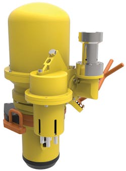
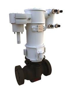
GE has a long history supplying subsea electric system components including subsea controls, electric actuators, power systems, and condition monitoring. Its portfolio of subsea actuators includes rotary or linear, low to high power, low to high torque, functioning over a range of operating speeds.
The company’s GE IFOKUS electric actuators can be powered and controlled either through the production control system, by trickle charging and storing energy in an integrated energy management system, or fed directly from a dedicated power source. GE IFOKUS rotating electric actuators for chokes and non-safety rated valves talk to the control system through a SIIS level 2 CAN or MODBUS interface – protocols that are widely used and accepted throughout the industry.
The power drawn by the energy management system is typically 48W or less during charging and well below 10W in stand-by. Adaptations are feasible where available power is limited. The aim is to ensure electric actuators can be added as easily as an extra instrument. Their limited power draw and flexibility in terms of input voltage, makes them well suited for brownfield and retrofit applications.
For subsea compression, the fast-acting GE IFOKUS anti-surge actuator was developed specifically to protect the compressors in the system. This is a linear actuator with torque capabilities up to 80kN. The solution is currently in operation at Statoil’s Åsgard gas compression project in the Norwegian Sea. It was also used in Norske Shell’s Ormen Lange Pilot project in the same region, the world’s first full-scale integrated subsea gas compression system with a full subsea power supply, transmission and distribution system. Between 2011 and September 2016 the system operated under an extended test program in submerged conditions with real hydrocarbons at Shell’s test facility at Nyhamna, western Norway. Gas from the Ormen Lange field is sent via a subsea pipeline to Nyhamna for processing.
Among the other GE technologies employed for the Pilot were the 12.5-MW, vertically-oriented centrifugal Blue-C compressor, specifically designed for subsea operation; subsea switchgear supplying power and protection to multiple loads from a single cable to shore; subsea variable-speed drives that take output from the subsea switchgear, providing the optimal frequency for the individual supply lines feeding the compressor; a subsea uninterruptible power supply providing power and protection to all the subsea compression station auxiliary loads; and a Mecon Dry-Mate connector 145/700 that enables power transmission at 145 kV for a 120-km (74.6-mi) tieback distance
The Snøhvit field that Statoil brought into operation in the Barents Sea in 2006 was another milestone. The fiber-optic communication system, controlled from onshore in Hammerfest, extends out to wells up to 220 km (137 mi) offshore, is matched by a long distance three-phase 3-kV power supply system that also carries a back-up communication channel superimposed on the power lines.
Hostile subsea conditions pushing boundaries of HP/HT valves
Paul Shillito
Oliver Valvetek
Deep subsea wells are a hard target, with the high pressures and temperatures presenting a significant design and engineering challenge. Any well at a temperature above 150°C (302°F) and 15,000 psi (1,034 bar) is defined as high-pressure/high-temperature (HP/HT), and all equipment used on the application – notably the valves – must be tested and rated to contain the produced fluids. Engineering subsea valves that need to be in service for two decades or more demands careful selection of materials, a high level of manufacturing precision, and comprehensive performance testing.
Subsea valves are pressure vessels. In order to contain the pressure inside, the walls of the valve are placed under tension that acts around their circumference. Mathematical modeling features extensively in the design process to ensure the valves have a pressure envelope that is sufficient to contain both the high pressures and temperatures inside and the pressures on the outside.
With conventional medium-pressure valves a thin-walled pressure vessel model is used to perform calculations for pressure containment. This model assumes that the cylinder walls are no more than around 10% of the thickness of the valve’s overall radius. A potential downside of this approach is that, when pressures get very high and valve walls become much thicker, the model can significantly underestimate the level of stresses within the wall thickness. In these instances, standards such as ASME VIII Division 2 recommend use of a thick-walled pressure vessel model.
However, for HP/HT designs, the calculations must extend to take into account local failure due to excessive strain, ratcheting effects and fatigue. In addition to the normal pressure changes associated with a valve being pressurized to working pressure, then depressurized to ambient, fatigue assessment must consider the fluctuations at normal working pressure. In some instances, the stresses due to HP/HT can lead the valve designer to discard normal linear elastic design practices in favor of elasto-plastic models.
Material challenges
The two main factors that can cause an HP/HT valve to fail are formation of stress fractures in the valve’s casing – a situation that could lead to a blowout – and, potentially less catastrophic but just as important, leak paths through the seals that allow the fluids carried to slowly escape into the environment. Attempting to contain hydrocarbons at pressures of 20,000 psi (1,379 bar) and temperatures of 200°C (392°F), with near-zero risk of either of the above hazards occurring, pushes material characteristics to their limit, and this is leading to increasing development and take-up of exotic alloys.
For years 718 stainless steel has been the material of choice for the top-performing HP valves. However, as pressure and temperature requirements rise, this material – although a high-performing, nickel-rich alloy – is reaching its performance limits. Above temperatures of 150°C, the pitting resistance of the material is not suitable for exposure to seawater.
The latest-generation HP/HT valves are now being made from 725 nickel alloy, a cutting edge material that was first produced by material scientists less than 30 years ago and was first developed for industrial use in the 1990s. However, ultra-high temperatures cause a reduction in the strength of the material. In the latest edition of API 6A, de-rating factors have been published for a wide range of materials for operating at temperatures of 150, 180 and 200°C (302/356/392°F). These de-ratings impose further complications on the designers’ mathematical models.
Another pressure-point is the gland seal of the valve. HP/HT units tend to operate with various types of media: in addition to produced fluids, the valves are required to operate with various types of chemical injection and hydraulic fluids. Normally these will be made from thermoplastics such as PTFE or PEEK, but their reduced physical resilience at temperatures around 200°C makes a guaranteed perfect seal a real challenge.
Approval testing
Oliver Valvetek has developed a range of small-bore valves rated for pressures up to 20,000 psi and temperatures up to 204°C (394°F). Achieving this rating for subsea equipment was a key goal, as it will both open up new extreme HP/HT opportunities.
The valves are in different configurations to suit flange, weld and threaded end connections. This will allow them to serve subsea applications including test, isolation and chemical-dosing lines. Before any valve is approved for service, prototypes must be thoroughly tested in conditions that simulate and go beyond the pressures, temperatures and dynamic movements that valve will face once in position on the sea floor. The mandatory tests are specified in the standards ISO 10423 and ISO 13628-4, however most operators have their own criteria that exceed the levels described by ISO.
Testing for the new small-bore valves involved high and low temperature cycling – i.e. opening and closing – the valves through multiple operations at the maximum pressure and temperature limits simulated. In reality, many of these valves will be used on applications where they will only be cycled a limited number of times in their operational lifespan, so the testing builds in a significant safety margin.
Developing new valves to stand up to the extremely demanding conditions of HP/HT wells is a laborious and expensive process, with the initial valve design taking over a year to move from the drawing board to first completion. However, as energy companies target ever deeper, hotter and higher-pressure wells, the economic incentive for the industry is clear. •
Deep Down announces new station-keeping system
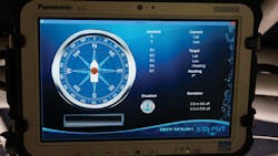
Deep Down Inc. recently introduced Sta-Put, a station-keeping system for use on lifeboats and other types of specialized vessels, including support and survey.
Company officials say that the joystick-controlled system was designed to simplify intricate and expensive dynamic positioning systems. In reducing the size and complexity, the company found it could install station-keeping systems into smaller vessels, opening the door for a new class of vessel operations that require less investment. Providing the ability to maintain position automatically andWhen installed on lifeboats, Sta-Put’s “Go Home” button enables a released vessel to automatically return to the correct lifting hook position. The boat can move in any direction with a touch of the joystick control, and can maintain position utilizing the compact on-board computer, continuous duty bow thruster, stern thruster, and existing conventional propeller, and rudder. This serves to eliminate much of the former stress and time associated with mandatory lifeboat drills or emergencies.
Deep Down officials say that the Sta-Put system has successfully undergone sea trials.
In addition, the company has conceived of a non-classed multi-purpose vessel that features the Sta-Put system. The vessel can operate above 20 knots when carrying crews and/or equipment. Manned by a small crew cross-trained in marine and remotely operated vehicle (ROV) operations, it can transition into Work Cat mode. The vessel would have a work-class ROV with video telemetry and can broadcast the ROV signal to a remote location. HSE and security is also provided through incorporation of thermal cameras and CCTV.
AssetWise APM offers enhanced integrity and reliability solutions
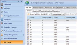
Bentley Systems says its AssetWise APM helps integrity and reliability engineers working with SAP Enterprise Asset Management (EAM) to develop programs that support risk-based inspections processes. With a view to the SAP Portal in real-time, inspectors and maintenance technicians are empowered with the information they need, when they need it – in the field.
The SAP Portal view in AssetWise APM displays the following information:
- Functional location and equipment assets
- Functional location, equipment, and operations task lists
- SAP maintenance items
- Standard maintenance plans.
With access to SAP EAM asset and work history, AssetWise APM users can navigate assets geospatially and get immediate feedback when condition readings are out of allowable tolerances. The asset health dashboard consolidates and analyzes all condition data from inspections and real-time monitoring devices, which facilitates more timely and accurate decisions on corrective actions. Bentley says that AssetWise APM’s certified integration with SAP EAM ensures that organizations using these systems together can drive a proactive process to manage asset reliability and integrity.
Other new capabilities in AssetWise APM include dashboards for strategy development analyses. These dashboards help identify the risk associated with asset failure and dynamic measurement points and accurately track and analyze data from locations that cannot be predetermined. This latter capability will be applied to subsea pipeline inspections conducted by ROVs.
The information collected in dynamic inspections is much more than the reading value and date collected. In the case of subsea inspections, it includes:
- • Where is it – location, depth, length, area affected
- • Conditions – water temperature
- • Anodes, berms, debris, span, marine growth, burial information.
Rob Churchman, senior director, product advancement, Bentley Systems said: “Our users depend on AssetWise working seamlessly alongside SAP to ensure assets are safe and reliable. The SAP Portal view within AssetWise APM has been so successful that we have expanded the capabilities further to drive higher levels of asset performance.”
Corrosion inhibitor enhances integrity of platform caisson legs
United Arab Emirates–Abu Dhabi Marine Operating Co. effectively reduced corrosion rates in an offshore platform caisson leg by using Vapor phase Corrosion Inhibitors. The company is a major producer of oil and gas offshore Abu Dhabi in the United Arab Emirates and operates multiple barge-type offshore platforms constructed on caisson legs.
A fatal explosion occurred at one of these platforms due to gas build-up inside the confined compartment around one of these caisson legs. The gas was found to be hydrogen generated by the depleted anodes inside the leg.
Internals of the platform caisson legs had previously been left uncoated, filled with biocide-treated water, and protected with suspended sacrificial anodes. Over two decades, the anodes had depleted inside the caisson legs and accumulated along with biocide water and blasting grit. An investigation of the explosion recommended the removal of these accumulations, and an alternative environmentally friendly method of protection was considered.
A successful pilot study was conducted in 2009 to evaluate the use of Cortec’s Vapor phase Corrosion Inhibitors (VpCI) to rectify the problem. One caisson leg was emptied and preserved with VpCI, and carbon steel weight loss corrosion coupons were used to assess the effectiveness of this approach.
Unlike traditional contact corrosion inhibitors, VpCIs have a moderately high vapor pressure that allows them to function in the vapor phase without applying VpCI directly to the metal surface. Therefore, VpCIs provide protection in the liquid phase, vapor phase, and critical interphase. VpCIs access the most difficult to reach spaces and provide effective protection against crevice corrosion.
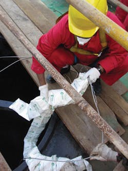
As part of the preservation process, Cortec says its ready-to-use waterborne corrosion inhibitor VpCI-337 BD was sprayed inside the caisson leg to prevent corrosion and bio-growth. Water-soluble, biodegradable VpCI-609 S powder was then fogged into the void space to counter the dead volume of water at the bottom of the leg. Custom manufactured strips of Cortec’s easy to use EcoPouch were suspended from above for additional protection. These EcoPouches were filled with VpCI-609 powder and constructed from breathable Tyvek, which allows VpCI molecules to be emitted through the membrane to form a protective molecular layer on metal surfaces.
The results showed strong improvement in the VpCI-treated caisson leg. Corrosion was kept at low rates considered acceptable. After two years, Cortec VpCI inhibitors had proved to effectively mitigate corrosion in an offshore environment, reducing the corrosion rates in the protected leg by 584% compared to the control. The pilot project was deemed a success and the methodology was adopted for treatment of all other caisson legs at the complex.
Zinc-rich epoxy coating offers corrosion protection alternative
A highly saline atmosphere, extremes of temperature and severe mechanical stress creates specific challenges for those needing to protect their offshore structures from corrosion. Failing to adequately guard against these harmful effects will cost dearly in terms of shortened asset life, increased maintenance costs and more downtime.
The conundrum for the offshore industry is having to make a choice between treating their structures with zinc-rich silicate coatings that offer higher protection but lower mechanical strength, or zinc epoxy coatings which are stronger but historically deliver less protection. The ideal is a combination – high levels of protection against corrosion coupled with the mechanical strength to prevent cracking and splitting.
Following many years of research, Hempel has developed a technology called Avantguard. This is a zinc-rich epoxy coating that exhibits the strength of a traditional epoxy alongside anti-corrosion properties. It does this by combining the ingredients used in traditional zinc epoxies with two new elements – hollow glass spheres and a proprietary activator. This makes the zinc much more effective in altering the electro-chemical reaction between salt, water and oxygen that allows the zinc particles to “rust” instead of the underlying steel structure. By enhancing the performance of zinc in this way – known as the galvanic effect – Avantguard is able to outperform conventional zinc epoxies.
Galvanic protection is just one of three properties delivered by Avantguard to ensure the required levels of anti-corrosion. Activated zinc also has a high tendency to form insoluble salts throughout the film that makes it less permeable to water penetration – this gives it its barrier properties. These salts also act as environmental scavengers and react with the chloride ions to reduce the movement of corrosive elements through the coating – the inhibitor effect.
Continued exposure over extended periods often cause micro-cracks in the paint, which will eventually lead to real cracks and corrosion. The hollow glass spheres within Avantguard absorb most of the stress from the initial cracks and prevent them from worsening. The sub-products formed during the zinc activation process will then occupy the micro-crack and stop it from developing into something more serious. This significantly reduces rust creep helping to ensure the coating retains its anti-corrosive properties for much longer.
But a coating must also be easy to apply. Often, in order to achieve excellent galvanic properties, a coating will contain a high concentration of zinc pigments that makes it hard for the paint to adhere to the steel surface and can also lead to “mud-cracking.” The activated zinc technology in Avantguard overcomes these problems and even allows a recoat interval of just one hour (at 20°C) which increases productivity for applicators.
Avantguard products are increasingly being specified to extend the lifetime of their structures and reduce maintenance costs.
Integrated riser monitoring system enhances multi-well fatigue life planning
Nick Stringer
Aquaterra Energy
When considering multi-well campaigns and the fatigue damage accrued through cyclic loading, traditional methodologies to accurately assess performance and integrity are failing to address the level of precise data management now required by the industry. Improved techniques should be used to create a clear, concise history of all component parts. Use of this information is also lacking when planning which riser assets should be used in the field and when inspection, repair or replacement is necessary. This area of concern is receiving greater attention in the North Sea, where riser systems are being increasingly used for large, multi-well campaigns lasting a number of years.
Aquaterra Energy developed the Riser Monitoring System (RMS) to provide integrated monitoring and analysis based on structural mechanics principles, underpinned by strain-based measurement. This integrated approach provides “monitoring with meaning,” which is the aim of Aquaterra’s monitoring systems. It has been developed to provide either real-time information or operate in memory mode, depending on project requirements. This aims to allow safe and detailed assessment of fatigue life based on measured riser strain. It also features an analysis methodology to facilitate asset life management and, possibly, life extension; minimize project risk; and provide planning of maintenance activities.
The RMS was recently deployed by a major operator in the North Sea to monitor a high-pressure riser deployed from a jackup.
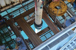
The RMS uses a combination of pre-installed direct riser strain measurement, subsea data logging, and processing algorithms to generate real-time information for drilling and workover operations. The system has been developed for jackup operations and can be deployed in water depths up to 120 m (394 ft). It is fixed to a typical riser joint in the stack-up. A strain-based measurement system was chosen, as this can be converted easily to assess fatigue damage, unlike accelerometer-based measurements. Accelerations are processed through a comparatively large number of mathematical steps to achieve fatigue damage, which can often lead to large errors and drift. Using strain improves the fidelity of the results. A mathematical transfer function is used to automatically map fatigue damage at any location along the riser system from one measurement point.
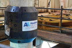
Specifically designed for subsea use, the RMS has four marinized gauges for strain measurement. Unlike conventional methods, abutment to the riser is by a specially chosen subsea epoxy resin, which ensures the strain data recorded is directly measured from the surface of the riser rather than the flex of any clamp used, which again, increases the fidelity of the measured data. Additionally, this abutment method was chosen to avoid fatigue hot spots caused by welding, which reduces the asset life. Heavy-duty housing provides maximum impact protection preserving the housed instrumentation and eliminating hang up during deployment and recovery. As the system is pre-installed and run on a standard riser joint, operational impact is minimized.
The data logger records all relevant information at a rate of 10Hz and has capacity to store up to 560 days of continuous data in its 32Gb memory card. It can be configured to store data locally, or instantly transmit the data to the surface for live evaluation, processing and reporting. This can range from short campaigns to up to a number of years of continuous service, without intervention. A single battery pack module powers the unit for in excess of 250 days with an option to include additional packs or powered from surface.
The measured strain data is automatically processed using a pre-defined multi-dimensional matrix, to deliver component fatigue utilization in real-time if necessary.
The RMS was recently used by a major operator in the North Sea to monitor a high-pressure riser deployed from a jack-up. A detailed riser analysis program took place before the system was deployed. An intrinsic part of planning the well, it ensures operations are safe in terms of a suitable operating envelope and required fatigue life. Once analysis has shown that the operation is safe to begin, it is desirable to precisely measure the events the riser experiences so that a more accurate representation of the fatigue utilization history can be recorded.
The product delivered a time-framed history of strain from the four strain gauges. This was then converted to bending, stress ranges and directionality. Subsequently, this information was processed using rainflow-counting and the pre-defined multi-dimensional matrix gave fatigue utilization against direction for each constituent component along the full riser length, to meet the client’s needs.
The value of using the system for this project was evident as it demonstrated the increased accuracy levels that can be attained compared to an analytical-only approach. The system was able to identify key differences in the results compared to those expected from the initial analysis. For example, as the system accounts for strain directionality it also showed that, during the drilling campaign, the loading direction from environmental conditions differed from the expected metocean conditions.
This information is then input into Aquaterra’s riser management system, which details the complete run history and fatigue utilization for each asset. This management tool is then used to inform maintenance and repair activities, ensuring the riser asset is fit-for-purpose and ready for future use.
Fatigue damage and cracks in oil and gas risers can potentially cause severe financial, reputational and safety consequences. Analyzing long-term fatigue performance and asset life expectancy is complex and experience from previous projects and from the field has shown that RMS-based measurements can be more accurate and/or less conservative.
By improving fidelity in data analysis, integrating fatigue monitoring and fatigue tracking systems, operators can be assured that better-informed decisions can be made based on accurate loads the riser system has been subjected to. This information can then be used with confidence by drilling companies to plan maintenance activities, which will ultimately increase safety and integrity of the riser system and potentially extend asset life.
