Fourth generation design
Rick Johnson, J. Ray McDermott, Inc.
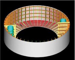
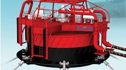
If the first three generations of spar technology can be characterized by the classic spar, the truss spar, and the cell spar, the fourth generation is characterized by the ring spar. Although hydrodynamically similar to the truss spar, this new hull configuration offers a reduction in the cost of hull fabrication through an alternative structural system for the hard tank section and several ancillary variations in its marine systems.
The new hull configuration addresses the construction issues around the fabrication and assembly of the spar hard tank components. The new hull configuration focuses on improved structural efficiency and constructability. It reconfigures the framing such that it becomes more construction-friendly for the contractor. This improves the overall cost and schedule of the project for the customer while also addressing safety issues around compartment confinement, above ground working areas, ease of inspection and increased shop fabrication. The opportunity to standardize hull components opens doors to subcontract more components and become more competitive.
Structural system
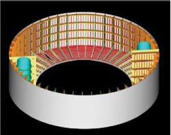
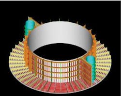
The hull is divided into sections by watertight flats. The flats are stiffened with structural angles curved to form concentric circles that are in turn supported by the radial girders spaced around the flats and spanning between the inner and outer-shells. In each section, longitudinal girders spaced radially around the inside of the outer-shell terminate at the flats and attach to the flats but do not penetrate them. The longitudinal girders are attached to flats aligned with the locations of the radial girders that extend across the flats to the inner and outer shells.
A panel stiffening arrangement on the inner circumference of the outer shell is attached to the outer shell and the longitudinal girders. Longitudinal girders spaced around the outer circumference of the inner shell extend along the length of the inner shell and are attached to the radial girders.
With the inner and outer longitudinal girders connected to the radial girders, moment resisting frames are created that are arranged radially in each compartment. These frames stiffen the individual girders as well as balance the differential axial loadings in the inner shell and outer shell surfaces. The compartments are assembled with the sections in a vertical orientation to minimize self-weight distortion during erection and to provide direct access with shop cranes during assembly of the full sections. The completed sections are rotated to the horizontal to be joined to the other sections to form a complete cylinder.
The key optimizations incorporated into the hull are:
• The primary shell plate stiffening is made with vertical girders (constant depth or tapered) spanning directly between the flats. Longitudinal girders are used on both the centerwell and outer shells.
• The outer shell has a three-level hierarchy of stiffening which uses intermediate ring girders to deliver the loads from the longitudinal stiffeners (angles) to the longitudinal girders.
• The stiffening of the flats is located on the bottom of each compartment (on top of the plate) instead of on the top of each compartment (on the underside of the plate). The purpose of this is largely to facilitate personnel access for the periodic hull inspections.
• One set of four radial bulkheads was added to the top compartment replacing the diagonal bracing in the lowest compartment. These bulkheads at this location create a strong shear-type tie between the center well shell and the outer shell. They also provide compartments for seawater ballast for the offload and wet tow as well as supplement the seawater ballast volume available in the truss legs.
• Foundations in the hard tank for the chain jacks, fairleads, topside legs and truss legs are made by locally stiffening thickened bands of heavy plate at the top and bottom of the hard tank instead of using smaller, local heavy plate inserted into the thinner shell plate.
Orthotropic stiffening for outer shell plates
The outer shell plating has a three-tier, orthotropic stiffening system that is orthogonally stiffened with longitudinal girders (between flats), transverse ring girders through the longitudinal girders, and longitudinal stiffeners through the ring girders.
The local panel on the outer shell, consisting of the longitudinal stiffeners and transverse ring girders, has a robust buckling capacity for the lateral pressure and transverse loads due to hydrostatic pressure as well as the longitudinal loads due to global motion. Also, the independent nature of the individual longitudinal girders on the outer shell stiffening system offers significant reserve strength in the case of member failure due to collision damage to one or several of these girders.
The longitudinal stiffeners provide increased buckling capacity of the outer shell plate but the area and geometry of the shell plate itself, in combination with the longitudinal girders, provides ample section modulus to carry the global axial and bending loadings of the outer shell. These stiffeners do not need to be continuous through the plate, which eliminates considerable amounts of specialized detailing and fabrication.
The end connections of the longitudinal stiffeners near the flats are of two types.
• Connection above the flat: These ends are sniped to land on the flat plate to form a simple shear connection but no moment connection. At the deeper levels where the hydrostatic loadings are more severe, these ends are connected with brackets to the first curved stiffener on the flat.
• Connection below the flat: These ends are terminated against the uppermost ring girder in the compartment. The space between this ring girder and the flat, generally 1 ft 8 in., is left clear to facilitate the shell plate fit-up and to make and inspect the shell plate splice between compartments.
One of the most important structural elements in the hull design is the longitudinal girder.
The key design loads for the hull hard tank are transverse stresses due to hydrostatic pressure and the longitudinal stresses due to global bending moment. In the most severe cases, the scantlings of the hard tank may be controlled by buckling of panel under the above two stresses. The longitudinal girders are the key structural elements preventing local panel buckling while also supporting the ring girders and working with the shell plates to carry longitudinal loadings in the stiffened shells.
Centerwell circular plan
The centerwell is stiffened by only longitudinal girders. Without radial bulkheads, this stiffened shell is in tension under all loadings over nearly all its length. To prevent the buckling of the longitudinal girders from axial compression due to global bending and hydrostatic pressure on the bottom of the hard tank, tripping brackets are included at the midspans of these girders.
Previous hull designs used local sections of thicker material inserted into the shell plates at each location of an equipment and leg foundation. To simplify this and smooth out the load transfer into the hard tank, continuous bands of thicker plate replace the regular shell plate at the top and bottom of the hard tank. The thickness and grade of material within a band can vary and still retain the fabrication advantages of the bands compared to individual inserts at each foundation.
All the radial girders and stiffeners are face-up (on top of) the flats. This was done to enhance access for inspection but it also avoids flipping the flats in the yard after stiffening.
The key aspect of this new fabrication technique is the ability to perform more work under roof while reducing the amount of exposure to the natural elements. It also enables the components to be assembled in a more “friendly” manner while easing the task of erection of large components on the skidways.
Hard tank subcomponents or quarter sections of the flats, outer shell and center shell, will be fabricated in fabrication shops, beginning with the assembly of flat plate panels, or blankets, that will make up the deck flats or shell plates. Plate blankets are made up from individual sheets of plate that will be cut to size on the plate cutting tables then moved to a designated area for assembly.
Blankets for deck flats will be fit up as “half ring” sections to assure dimensional accuracy, but with one weld seam left un-welded so that the completed deck flat half rings can be separated into quarter sections for transport to the fabrication buildings. After welding of a plate blanket has been completed, layout and installation of structural members will take place.
Assembly of the deck flats begins with the layout and installation of the rolled angle stiffeners onto the plate blanket. Once welding of the rolled stiffeners has been completed, installation of the radial girders takes place. Final NDE and dimensional checks will be performed, and when accepted the components will be complete and ready for painting, as required, and transport to the fabrication building.
Assembly of outer shell and centerwell components will begin with the layout and installation of the longitudinal angle stiffeners onto the completed plate blankets. The plate blankets, with longitudinal angle stiffeners installed, will then be lifted and set into jigs so that the shell plates will conform to the required radius. Once the shell plates have been secured into the jigs, the transverse girders can be installed followed by the longitudinal girders.
Final NDE and dimensional checks will be performed, and when accepted, the components will be complete and ready for painting, as required. The completed components will be painted and transported to the fabrication building where construction of ring sections will take place.
Construction of the ring sections in the fabrication building will begin with the quarter section of a flat being lifted and set onto temporary fabrication supports. Next, the outer shell quarter section will be lifted and set onto the flat.
Once the outer shell section has been tied in, the radial bulkheads will be set in place and tied into the flat and outer shell structures, followed by the center well sections. The access shaft sections will be installed along with as many appurtenances, supports, stiffeners, piping, etc. as practical, subsequently completing assembly of each ring. The completed rings will then be transported to the assembly area.
Yard assembly
The completed rings will be transported from the fabrication building to the assembly area using multi-axle trailers and placed on temporary supports.
Two each adjacent ring sections will be stacked and joined together resulting in three hard tank modules approximately 60 ft tall. The top hull ring, containing two flats, thus being assembled as a closed compartment, shall be considered an individual module. All other ring sections will have an open end where temporary braces shall be installed for roll-up support and to ensure dimensional integrity.
Each consecutive module will be transported to the erection area with multi-axle trailers and positioned between the skid-ways where it can be lifted with a mast jacking system, rolled into the horizontal position and set down onto the skid-ways.
Each consecutive hard tank module shall be transported, rolled up and set onto the skidway. The modules will then be moved down the skidway for fit-up to the adjacent module. Once the modules have been rolled up and placed on the skidway, the towers of the mast jacking system shall be partially dismantled and re-assembled at the north end of the skid-way for the roll-up of the final module.
Through the use of constructability, techniques have been improved for the fabrication and assembly of the hull components. Optimization of these techniques results in lower cost and improved schedules.•
Acknowledgments
The author would like to thank Robin Converse and Young-Chan Park for their vision and persistence in developing a more competitive industry solution for the spar.
The author would also like to thank J. Ray McDermott, Inc. Engineering and Fabrication groups for their input and efforts.


