The rehabilitation of a leaking subsea check valve on an operating gas line operating at 1,160 psi was completed by Mexsub using a sleeve system to encase the valve. The repair, which was conducted in the Bay of Campeche offshore Mexico, did not require shutting down the pipeline or reducing flow, or welding on the valve body.
A sleeve system designed by Mexsub was used. The valve was a Grove C-5 check type with a spring return clapper installed on a 36-in. subsea gas transmission line in 105 ft water depths. Leakage was occurring at the spring return canister. Mexico's national oil company, Pemex, required the line to be rehabilitated without altering flow.
The sleeve system is approved by DNV with a type approval certificate as a "Permanent Repair for Pipelines and Risers." This approval allows DNV to re-certify the repaired section of line, following repairs to original design parameters.
This project required sleeve sections weighing 7 tons with a diameter of up to 150 in. to be installed directly over the spring return canister. To use a sleeve of this magnitude, several modifications were necessary in the subsea habitat and the installation procedure.
Installation procedures in this case allowed for seating the habitat over the sleeve after the sleeve was in place. Welding procedures along the longitudinal and circumferential seams would be conducted with seawater partially filling the annular space. This would prevent excessive buoyant force on the pipeline.
Measurement, fabrication
Pemex originally identified the leakage during a regular inspection. The damage was videotaped and the information provided to Mexsub. The firm conducted a follow-up inspection with their divers to confirm the measurements necessary for sleeve fabrication. A special set of calipers was fabricated by Mexsub to allow for exact diameter measurements around the valve, spring return canister, and at the pipeline where the sleeve would be welded to the original line.
The sleeve was fabricated using ASTM A-515 Grade 70 steel with a wall thickness of 0.875 in. The two sections were hinged along one of the longitudinal axis to allow placement over the valve and exact alignment of the welded bevels. A bolted flange connection was fabricated on the upper section to allow placement and sealing of the habitat. Guards and dampeners were incorporated into the design to prevent damage to the spring return canister during installation.
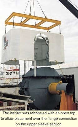
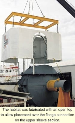
The habitat was fabricated with an open top to allow placement over the flange connection on the upper sleeve section. A bolted connection with a neoprene gasket would be used to seal the habitat over the sleeve, following its placement on the check valve.
Additional considerations addressed in the fabrication of the habitat included emergency breathing and communications equipment. These safety considerations were necessary because a dynamically positionined (DP) vessel would be used as the primary support vessel on this contract. Pemex required DP, as opposed to an anchored vessel, due to the number of pipelines in the area.
Site preparation
Mexsub contracted with Cal Dive International to use the Witch Queen as the primary support vessel for the contract. The Mexsub vessel Jaguar provided additional support. This vessel was configured specifically for Mexsub riser and pipeline rehabilitation projects.
Excavation of the valve was conducted using a 14-in. airlift line with a cutting head. The total area excavated was approximately 15 sq ft to a depth of 9 ft below the seafloor, this allowed ample space for the placement of the sleeve and habitat.
The sleeve sections were lowered to a depth of 70 ft using the support vessel crane. At this depth, divers attached air bags to pre-installed padeyes, and the bags were inflated to reach neutral buoyancy. Guide wires were threaded through the sleeve sections and tensioned to the surface using flotation buoys.
The crane was then disconnected and the sleeve lowered in the open position using the guide wires to place it in final position over the check valve. Control of the sleeve during this process was isolated to the divers who controlled the pressure in the air bags. The sleeve was then slowly closed and the longitudinal seam opposite the hinge was secured with bolts.
Using the air bags, the sleeve was rotated until the longitudinal seams were aligned with the horizontal axis of the pipeline. At this point, the air bags and guide wires were detached and returned to the surface. The habitat was placed in position over the sleeve using the crane aboard the support vessel. Following its placement over the sleeve, the top flange connection was bolted and sealed and the habitat was sealed around the pipeline.
The habitat was then pressurized with pure helium to displace the seawater to a level immediately below the longitudinal seam of the sleeve. This represented about 85% of the volume of the habitat.
Welding, weld inspection
Welding along the longitudinal seams was conducted using two diver/welders in the habitat. During the welding process, the habitat was continually flushed with helium and oxygen monitors were used to ensure no oxygen contamination. E-6010 rods were used for the first pass and the hot passes, and E-7018 rods were used for the filling and dressing passes.
Following completion of the longitudinal welds, diver/inspectors entered the habitat and inspected all completed welds using ultrasonic testing. Certification on the integrity of these welds was completed prior to the final welds on the circumferential area connecting the sleeve to the original pipeline. Identical welding procedures were used on these welds, which were then inspected and certified.
Resin injection
At the completion of the welding process, the annular space was pressurized with helium to displace all remaining seawater and leaked product, which was vented to the exterior of the habitat. The annular space was then pressure washed with fresh water twice before being re-pressurized with helium.
The specially formulated epoxy resin was injected in three stages to reach a fill of the entire annular space. The sleeve system uses epoxy resin formulated for the problem being addressed in a specific repair, to fill the annular space and completely integrate the original pipeline and the sleeve.
Following successful resin injection, the pipeline was stabilized with sand bags and re-buried. The sleeve system was designed to allow rehabilitation of risers and subsea pipelines without suspending production. It allows for installation over different geometric configuration of the pipeline such as bends, Ys, Ts, and other forms.
Specific causes for accelerated rates of corrosion and erosion (such as high temperature or internal abrasion) can be addressed through changes in the annular space and the formulation of the resin used to integrate the original pipe and the sleeve.
