Calum MacKinnon • Acergy
Jason Stanley • Schilling Robotics LLC
Technology for remotely operated vehicles (ROVs) has evolved rapidly over the last 20 years, driven mainly by the need to support deepwater field development. Most deepwater intervention operations are now beyond diver depths, so the performance of the ROV system is a vital factor in the success of the offshore operation.
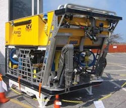
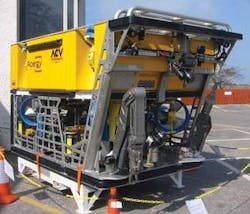
As part of Acergy’s investment in its new ROV fleet, the Acergy Core Vehicle (ACV) system has been designed to enhance operational efficiency. The program involved implementing improvements to all equipment components, from the launch and recovery system to the tether management system (TMS), the ROV itself, and even the control console. The design process also required careful review of the work involved in deck operations, deployment to the worksite, subsea navigation and positioning, and intervention tasks.
The ACV, developed jointly by engineers from the Acergy group and Schilling Robotics LLC, provides two major improvements in intervention performance. Firstly, the vehicle can handle a high level of tooling located either within its center deck area or mounted externally. Secondly, its StationKeep control and positioning system provides an accurate subsea dynamic positioning capability.
Launch and recovery
One of the main targets in this project was high speed and precise control of the launch and recovery systems (LARS), for the following reasons:
- Rapid deployment/recovery through the splash zone widens the operating weather window
- High-speed transit through the water column to and from the worksite reduces deployment and recovery time
- Active heave compensation during the docking operation between the ROV and tether management system (TMS) avoids tether damage/parting.M
The company wanted a winch system with a compact footprint and low noise characteristics to suit the vessel locations. An electrically driven winch design was selected as an alternative to the traditional hydraulic system. Increasing the level of articulation of the horizontal A-frame position would enable the ROV/TMS assembly to be released at a much lower level, lessening the risk of impact damage against the vessel sides due to the pendulum effect. This was necessary for a number of vessel installations where the launch position was high above the water line.
The implementation of electric winches and enhanced A-frame systems also increases weather capability and the efficiency of the offshore operation during launch/recovery and transit to the worksite.
Center deck intervention
ROV systems used in construction projects typically have to operate a large variety of intervention tooling systems. On most vehicles, there is not enough space within the vehicle frame to accommodate these components, so they have been placed traditionally on an externally mounted tool skid either under the vehicle or on the rear face. But this configuration brings several disadvantages:
- Structural mounting onto the ROV frame can be complicated and time consuming
- Maneuvering the skids into position on the vehicle offshore may require a crane and can also be constrained by weather
- The component configuration in the tool-skid may affect the wash from the vertical or horizontal thrusters
- The size or position of the tool skid may affect vehicle dynamics and maneuverability
- The manufacturing cost of tool skids is typically doubled due to the structural framework and associated buoyancy
- Packing and transportation can also be expensive, and require a dedicated storage space on the vessel.
To address the problems associated with externally mounted tool skids, the ACV system incorporates a center deck space in the middle of the vehicle for onboard tooling, including a tooling slide on both the port and starboard sides. Ballast lead of 75 kg (165 lb) is provided in each slide area to provide 150 kg (330 lb) of tooling payload.
Installing center deck tooling on the vehicle is as simple as removing a corresponding weight of lead ballast, installing and securing the center deck module slide, and then hooking up to the vehicle’s plug-and-play services. The slides can accommodate a large variety of tooling components within their operating envelopes, and each vessel has numerous spare slides for ad hoc tooling.
The center deck modules provide the following advantages over externally mounted tool skids:
- Dedicated tooling envelope within the vehicle framework with a standard slide interface
- Easy on-deck handling, installation, and hook-up of the slide modules
- Positioned so they do not affect the vehicle thruster wash or vehicle maneuverability
- Easy module storage on workshop shelves
- Easy packing and shipping
- Low-cost construction, with no buoyancy or frame required
- Minimized on-deck turnaround time for tooling.
Center deck isolated hydraulic power units (IHPUs) have also been developed for the ACV and are compact and easy to transport both to the vessel location and between vessels at the worksite. They can be used on any ACV system and on a number of other vehicles when combined within a rear deck frame. The latter has the same slide interface as the center deck tooling module and is designed to mount on the rear face of existing Acergy SCV ROVs and most third-party vehicle systems, again slimming project cost and operational logistics.
External tool skid interfaces
The ACV vehicle can handle a large number of externally mounted tool skids or equipment items. The vehicle is fitted with the following structural docking interfaces on its framework to facilitate mounting of external components while increasing the operational flexibility of the vehicle:
- The underside of the vehicle is fitted with a traditional four-pin vertical docking interface rated for a 3,000-kg (6,614-lb) vertical load
- The front, rear, and sides of the vehicle are fitted with a bespoke four-point docking interface that uses the structural integrity of the vehicle’s top and bottom decks. These are each rated to handle a 1,000-kg (2,204-lb) vertical load
- The crash bar at the vehicle’s front top can also be rated to handle a 250-kg (551-lb) vertical load. This capacity is useful for mounting survey sensors and instruments.
Work basket skid
The vehicle can also be fitted with an under-slung hydraulically actuated work basket for general tooling support, which is used to store utility tooling such as cutters, grinders, torque tools, and hot stabs for easy access by the manipulator for ad hoc operations. These tools are permanently plumbed into the vehicle for ease of operation, and it greatly increases the vehicle’s operational flexibility.
Suction pump module
As part of the ACV tooling development program, a large-capacity suction pump system has been developed for pile installation operations. It is designed to interface to a standard structural interface frame on the suction pile, and includes a landing deck, bullseye, and water stab receptacle. The suction pump, control pod, and data logger pod components are configured to fit on a center deck slide for ease of handling and installation.
Pipe work from the pump is routed down through the work basket and then out the vehicle front to a 4-in. (10.16-cm) water stab. A flow meter fitted in the pipe work can accurately measure the pumping rate. The docking frame on the vehicle’s underside is equipped with two-off docking probes and a tailhook arrangement at the rear, which is mounted on the underside of the ACV work basket. It could also be mounted directly to the ACV or any other work class vehicle.
Subsea positioning
The ACV system also offers StationKeep control and positioning capability. This provides the operator with the subsea equivalent of vessel dynamic positioning, enabling the control system to take command of the vehicle and automatically maintain position relative to the seafloor. The ACV’s instrumented hydraulic motors further enhance direction and speed.
The main sensor in this process is a Doppler Velocity Log (DVL), which uses seabed tracking, altitude information systems, and data provided by the onboard motion reference unit and gyro to provide the vehicle with automatic flight control and the ability to maintain position in the X, Y, and Z axes.
The main operational benefit provided by the StationKeep is the ability to “park” the vehicle in any location with the confidence that it will stay in exactly that position until instructed to move. This negates any problems associated with platform pitch and roll, and allows the operators to accurately focus a camera on a specific target, perform a delicate manipulator task, or carry out training. Heading, altitude, position, and external forces, such as visibility and strong currents, are all maintained automatically, providing the operator with an exceptionally stable platform. This relieves the pilot from continuously having to fly the vehicle.
The system also enables the ACV pilots to change the methods of not only operating the vehicle but also performing intervention operations. By ensuring the vehicle’s position is maintained to suit the manipulator operations, less exertion is put on the five-function grabber arm, which often acts as a pivot point while the rest of the vehicle responds to forces exerted by the other manipulator or currents. The viewing angle is also opened and restrictions to the operating envelope of the seven-function manipulator are lifted.
While it aids in many intervention tasks, survey operations may not fully realize the benefits of enhanced control and automatic position capability. AutoTrack, a utility that allows surveyors to direct the ROV to move forward across the seabed along a designated survey line, is one of the ACV’s main survey applications to improve quality and speed of seabed survey operations. The control system keeps the vehicle on the designated survey line, closing the control loop with feedback from the survey system, and reporting any vehicle variances from the survey line. Other survey applications, such as riser inspection and pipeline inspection, will also benefit from this enhanced positioning and control capability.
Acergy Group and Schilling Robotics are continuing to develop enhancements to the ACV system and associated technologies, which, following full field testing, will be retrofitted on the rest of the Acergy ROV fleet:
- The layout control console is currently being reviewed to improve operator ergonomics. This development involves a “cyberchair” that features ROV controls and control monitors located on the pilot seat
- Applications for the StationKeep will be further developed to provide the ROV with even more options for positioning and maneuvering subsea
- High-definition digital video technology will be developed and implemented onto the ACV system to improve the quality of video capture, handling, presentation, and storage.
