Christian A. Cermelli, Dominique G. Roddier, Alexia Aubault • Marine Innovation & Technology
There are marginal fields with significant reserves that are not large enough to warrant a dedicated process platform nor close enough to an existing platform with spare capacity. These reserves may become economic if development costs can be reduced.
Subsea technologies have evolved to give better, more reliable functionality in greater water depths. A number of subsea technologies have been or are expected to be implemented soon to allow production from remote marginal fields in deepwater. Technologies expected to reduce the threshold of recoverable reserves for deep and ultra deepwater reservoirs include subsea separation, multiphase pumps, electrically heated flowlines, artificial lift with subsea electric pumps, subsea gas boosters, etc.
Power requirements for subsea applications are typically large, from 100s of kilowatts to 10s of megawatts. Power may come from a nearby platform, distant host, or shore, all of which can present issues. First, the power generation capability may not be available on the host, and the host payload may be limited, particularly in deepwater. Secondly, power transmission over long distances through electrical cable is costly and has technical challenges, including the conversion to lower voltages subsea.
The optimal development strategy may combine both subsea and surface equipment to maximize the potential of each technology. A minimal floater with sufficient payload capacity can be used to generate power for this equipment.
To be useful in this context, a minimal floater:
- Must not be manned normally, so that exposure to offshore personnel is reduced
- Must be accessible by boat and by helicopter for inspection or maintenance
- Must not require active ballast
- Must be sufficiently reliable to meet production targets
- Must respond to wind, waves, and current as well as existing floaters so topsides equipment does not require special provisions or additional testing; it must operate in a 10-year winter storm, and must be sufficiently stable to support steel catenary risers (SCRs) or umbilicals
- Must relocate easily, as marginal fields typically will not produce for many years
- Must be sufficiently low in cost to meet economic targets.
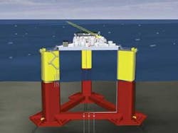
Marine Innovation & Technology has developed and qualified a minimal floater, referred to as “MiniFloat”, which satisfies these requirements and offers the ability to produce power locally and to provide payload for chemical injection, telecommunication, fuel storage, controls, etc.
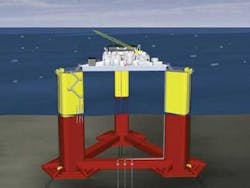
MiniFloat-III platform
The two main sources of offshore power are diesel engines and gas turbines. In the case of diesel, fuel may be supplied to the platform by vessels. Alternatively, a piggy-back line laid with the flowline can provide fuel from a hub. A third option is to process hydrocarbons from field production. This requires process equipment and a production riser. Gas also could be supplied to the platform by a piggy-back line from the hub.
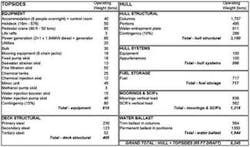
This minimal floating platform specifies 4 MW power generation requirement, and the ability to treat and inject 30,000 b/d of water via three SCRs. The total equipment weight on the deck is 600 tons (544 metric tons), 200 tons (181 metric tons) of that for water injection requirements.
The largest payload component is diesel fuel at 200,000 gal. in three tanks in the platform columns. This is sufficient for 37 days at maximum power. This assumes delivery of 700 tons (635 metric tons) of diesel monthly and a seven days contingency.
The platform normally is not manned. No active ballast is used to compensate for fuel because of risks of malfunction. The platform must to absorb the 10-ft (3-m) draft change resulting from the fuel payload and drawdown.
The MiniFloat is a three-column semisubmersible with a horizontal water-entrapment plate extending from the base of each column. Several feasibility studies have assessed the platform for various payloads. The smallest had 50 tons (45 metric tons) payload to power subsea instruments in Southern Ocean ultra deepwater. The platform, named MiniFloat-I, was less than 200 tons (181 metric tons) in displacement. At the other end of the payload spectrum, the concept was shown to support a 40,000-b/d of oil process facility with 2,000 tons (1,814 metric tons) of equipment in Gulf of Mexico metocean criteria. Displacement of the platform, labeled MiniFloat IV, was 14,000 tons (12,791 metric tons). For larger payloads, the conventional or deep-draft semisubmersible is more economical.
The main differences among the various MiniFloat platforms are the payload and displacements. The smallest versions have circular columns. The largest have rectangular ones. Various geometrical parameters, such as column size, spacing, draft, pontoon configuration, still-water airgap, etc. are adjusted based on the functional requirements. Weight for the MiniFloat-III power and water-injection platform reaches 8,245 tons (7,480 metric tons). Platform draft varies between 75 ft and 85 ft (23 m and 30 m); the distance from center to center of column is 150 ft (46 m) and the pontoons length is 110 ft (34 m). The columns are rectangular, 32 ft by 24 ft (10 m by 7 m) with 5-ft (1.5-m) radius of curvature, and the edges of the hexagonal water entrapment plates are 45 ft (14 m) long. The deck area is 10,000 sq ft (929 sq m) with 110 ft (33.5 m) unsupported span between columns.
Fabrication, installation
One key to the MiniFloat is that it can be fully integrated and pre-commissioned at quayside. In Step 1, the deck beams are assembled and the modules are placed onto the deck. In Step 2, the column and pontoon sections, and the water entrapment plates are assembled and welded. Steps 1 and 2 are simultaneous. The deck can be fabricated on the US Gulf Coast. The hull also may be fabricated on the Gulf Coast. Although cost may be lower in the Far East, transportation costs could offset any savings. It is assumed that the deck is fabricated at the integration site but the hull in a different yard.
In Step 3, after the hull is complete, skidded onto a transportation barge, and brought to the integration site, heavy lift cranes (3,500 tons [3,175 metric tons] lift capacity) lower it into the water. The deck is lifted onto the columns in Step 4, and connections between the hull systems and the deck are established. Pre-commissioning activities are conducted.
Step 5, pre-laying the six-lines mooring system, is done before completion of Step 4. There are two mooring lines per column. The mooring lines are the same size as those of mobile offshore drilling units rather than the larger size typically required for production platforms, and so can be installed with anchor handling vessels. This offers flexibility and cost reduction due to vessel availability.
In Step 6, the platform is wet-towed to its installation site. The platform draft in transit is 35 ft (10.5 m). The platform is ballasted to its operational draft and mooring line connection is completed with the AHV in Step 7. Chain jacks at the top of columns are used to pretension the mooring system to 300 kips.
SCR installation may be done a number of ways, depending on the available installation means, and whether the SCR are pre- or post-installed. A temporary winch may be placed on the top of column to assist the SCR pull-in process. A sheave would be installed on the beam supporting the deck directly above the riser porch. The beam is designed to support the SCR weight during installation and an additional load from an accidentally flooded SCR. The riser porches are on the outer side of one pontoon, and extend out from the deck. It is possible for an offshore construction vessel to lift the SCR into their porch while keeping a sufficient clearance between the lift wire and the deck.
To decommission, simply reverse the installation sequence.
Stability factors
The platform is a column-stabilized unit. Stability was verified in accordance with ABS rules for two operational draft conditions: 75 ft (23 m) draft when diesel tanks are empty and 85 ft (26 m) when full. For each draft, intact stability and three cases of damage stability covering the worst damage events were considered.
The columns are compartmented with four watertight horizontal flats at 18 ft, 36 ft, 65 ft, and 102 ft (5.5 m, 11 m, 20 m, and 31 m) above the keel. An 8-ft x 16-ft (2.5-m x 5-m) inner shaft runs continuously from the keel to the top of columns. Two vertical watertight bulkheads are placed inside each column, between the third and fourth watertight flats (at the water line level). Bulkheads do not extend across the inner shaft.
The platform includes three diesel tanks, one in each column. Accordingly, the intact stability of two intermediate configurations with unfavorable loading conditions also is considered, i.e. one tank empty and the other two full, and two tanks empty with the third one full. Since these are not normal-operating conditions – pumps draw an equal amount of diesel from all columns into a day-tank located on deck – no additional damaged stability cases were run.
Damage cases were as follows:
- The outer compartment of the downwind column is punctured at the waterline level
- The largest underwater compartment is punctured in the downwind column
- The inner shaft is flooded in the downwind column.
RhinoMarine software was used to determine downflooding angles and hydrostatic restoring moments. Internal free-surface effects from the ballast and diesel tanks as well as the effects of the mooring system on stability have been included.
The safety factor in intact cases is represented by the ratio of overturning over righting moment areas up to the downflooding angle. In the empty case, safety factor in intact condition is 3.6; in the fully loaded case, it is 3.0 assuming the downflooding points to be at the column top. These compare to the minimum safety factor of 1.3 required by ABS. The unbalanced configurations with one empty diesel tank and two empty diesel tanks yield safety factors of 2.8 and 2.0, respectively. The maximum heel angle under a 100 knot wind is 5.3° in the empty case and 11.4° with two empty diesel tanks.
The damage analysis shows that a maximum 11.5 degrees heel angle is achieved in a 50-knot wind in fully loaded configuration and 14.5 degree if empty. Safety factors in all cases range from 1.8 to 2.6.
Hydrodynamic analysis, model testing
The MiniFloat concept water-entrapment plates at the base of each column provide a large hydrodynamic inertia in heave, pitch, and roll, allowing the platform natural periods in these three degrees of freedom to shift beyond the wave period range. This minimizes wave-induced motions while keeping platform weight and displacement small.
The water-entrapment plates are exposed to wave loading in large sea-states. WAMIT diffraction-radiation software computed the interaction between the floater and the waves. The water-entrapment plates are modeled with dipoles, numerical elements developed to represent the flow around thin surfaces. The platform motion was computed using the TimeFloat software, which calculates mooring line dynamics using a finite-difference model, and solves the equation of motion of the floater in the time-domain. Viscous effects of vortex-shedding around the edges of the water-entrapment plates significantly affect platform response. These effects are modeled within TimeFloat using viscous elements placed along the edges of the water-entrapment plates. A modified Morison equation model generated quadratic viscous forces, perpendicular to the plate and proportional to the square of the relative velocity between the plate edges and the water particles. Empirical drag coefficients are validated by laboratory testing.
A model-testing campaign was conducted in September 2007 by Oceanic Consulting Corp. in the Memorial University of Saint John’s towing tank in Newfoundland, Canada. Test objectives were to:
- Measure platform responses in hurricane conditions, taking into account the interactions between the waves and current
- Confirm the airgap
- Verify that the lift force on the water-entrapment plate is minimal.
A 1/80 scale model of the MiniFloat-III was attached to the carriage with three mooring lines to provide the same stiffness as the prototype mooring system. The model was towed toward the wavemaker as waves were generated to simulate the combined effect of waves and current. The wind force was modeled with a pulley-weight system providing a constant force onto the model corresponding to the 1-min average design wind speed.
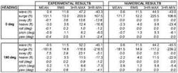
Four runs lasting 30 minutes in full-scale were performed in the 0° and 180° directions. Three-hour maximum values were obtained by fitting experimental data using a three-parameters Weibull function. One hundred-year hurricane environmental criteria for the western Gulf of Mexico location selected for this study are as follows:
- Significant wave-height: Hs=46 ft
- Peak period: Tp=14.6 sec
- Jonswap peakness parameter: g=2.5
- Associated one-minute wind speed: Vw= 127 ft/s
- Associated current speed: Vc=5.2 ft/s.
In the 100-year hurricane, maximum offset reaches 220 ft (67 m) or about 3% of the prototype water depth. Maximum heave remains below 20 ft (6 m) and maximum rotations below 10°. Results of corresponding numerical simulations agreed with experimental data.
Tests in regular waves were conducted at various trim angles. Small set-down of the model was observed with the forward speed but was independent of the trim angle, indicating that the water-entrapment plate does not generate significant lift.
Video-recordings were used to determine the platform airgap. The maximum crest reached 50 ft (15 m) from the still water level. Deck height is set at 55 ft (16.75 m) with the platform fully loaded (85 ft [26 m] draft). In the light draft case (75 ft [23 m]), the deck height is 65 ft (19.8 m) above mean water level. This provides a 5- to 15-ft (1.5- to 4.5-m) clearance in the 100-year hurricane, depending on the draft condition.
Structural analysis
ABS MODU rules cover structural sizing of semisubmersible platforms based on scantling formulas, which have been validated extensively for conventional semisubmersible designs. In the case of the MiniFloat, these scantling rules are appropriate for columns and pontoons. However, no suitable methodology is provided to verify the design of water-entrapment plates. Furthermore, the additional loading attracted by the water-entrapment plates is transferred to the rest of the structure, particularly to the nodes where the pontoon, column, and water-entrapment plate meet.
The water-entrapment plates are cantilevered steel plate reinforced with stiffeners and girders. Large radial stiffeners extend from the columns to the edges of the water-entrapment plate to carry the bending moment into the column. The water-entrapment plate is thin so the hydrostatic pressure difference between the top and bottom surfaces is negligible. The maximum dynamic pressure applied to the plate in the design sea-state is 1,500 lbs/sq ft (0.072 MPa). By comparison, the hydrostatic pressure applied to the column at the base is as high as 8,600 lbs/sq ft (0.412 MPa) in the same sea state.
Finite-element analysis confirms structural design of the MiniFloat-IV platform, a larger version of the MiniFloat with full-process capabilities. Earlier work was used to size the radial stiffeners holding the water-entrapment plates, as well as vertical bulkheads at the column base to carry the corresponding loads. Bracing tying back the radial stiffeners to the column was not necessary. The water-entrapment plate design was determined by strength rather than fatigue. The loading in smaller operating sea-states is reduced considerably as the shorter waves period decay rapidly with depth.
The MiniFloat-III platform hull is made of 36 ksi (248 MPa) steel. Total structural weight, including a 10% contingency, is 3,150 tons (2,858 metric tons), corresponding to a steel density of 11 lb/cu ft (176 kg/cu m) for the columns, 15 lb/cu ft (240 kg/cu m) for the pontoons, 17 lb/cu ft (272 kg/cu m) for the nodes and the water entrapment plate density is 78 lb/sq ft (381 kg/sq m).
Riser analysis
The MiniFloat-III supplies three water injector wells via SCRs connected to one of the pontoons at the porches.
Preliminary strength and fatigue analysis of the above steel catenary riser was conducted using the commercial software Flexcom-3D. Motion characteristics of the MiniFloat-IV platform were used as input. These are very similar to those of the MiniFloat-III platform discussed in this paper.
Fatigue life of 1,067 years was computed at the top connector and 2,925 years in the touch-down area. The minimum is the hang-off, which suggests that the contribution of the bending stresses towards damage is low compared to the axial stresses. The top angle for the water-injection SCR is high, which leads to relatively high axial stress while the bending stress is relatively low due to the small SCR diameter. Future optimizations will reduce the top angle. Due to the large safety factor, fatigue life likely will be acceptable with smaller top angle, resulting in lower maximum tensions. No compression occurs in 100-year hurricane sea-states.
