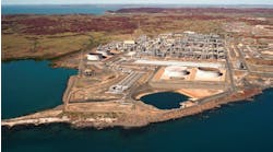
Statoil is developing the Åsgard Field, comprising the Smoerbukk, Smoerbukk South, and Midgard reservoirs in the Haltenbanken area, about 150 km offshore mid-Norway. The giant subsea development consists of 60 wells and about 300 km of infield pipelines tied back to an FPSO at Åsgard A and a floating gas-gathering center at Åsgard B. Midgard gas is extracted by three subsea templates (X, Y, Z) and transported via a 20-in. diameter, 95 km pipeline loop to Åsgard B.
Each template is tied in to the 20-in. gas line with 10-in. rigid spools connected to valve tees. The central Y template is tied in with two spools, straddling a 20-in. midline valve that allows round-trip pigging when open and dual-pressure operation when closed. ABB Offshore Systems - Pipelines and Risers in Norway has performed the detail design of the flowlines and tie-in systems, as well as providing construction support.
The Midgard flowline was installed using the S-lay method during August 1999. Starting at Åsgard B, the first section (Y102) was laid eastwards until it crossed the Haltenpipe, then turning south through a series of 90° turns past the X and Y templates. The second section (Y101) continued south from the midline valve at Y, past the Z template, before turning westwards back to Åsgard B.
Tee challenges
The verticality of the tees at the templates was a concern because previous experience demonstrated that pipelines can rotate as much as +/- 80° during laying in 300 meters water depths. Although twisting of the pipeline is not problematic for normal pipelaying, the difficulty in connecting to a tee is proportional to its deviation from the vertical.
Any unexpectedly large angles will result in increased duration of subsea tie-in operations and will require modifications to tie-in equipment. The Midgard valve tees were designed to accommodate the Icarus remote tie-in tool with a +/- 15° deviation from vertical, while contingency procedures were developed to accommodate +/- 30°.
Previous analyses demonstrated that twisting of a pipeline during laying is related to plastic straining while the pipe is on the overbend of the stinger, which results in residual curvature. When the bent section of pipe arrives in the sagbend and is subject to sideways displacement, it can release potential energy by twisting. The tendency of the pipe to rotate is amplified when laying pipe in a curve, of which there were four in the vicinity of the tees.
Therefore, the possibility of severe pipe rotation prompted an investigation to determine the extent of the problem and the effectiveness of possible countermeasures. This paper will describe the pipe rotation analysis methodology and the measured behavior during the installation of the Midgard flowline tees, including a re-analysis for comparison with the as-built configuration.
Rotation phenomenon
Pipeline rotation is caused by a torsional moment in the sagbend between laybarge and seabed that is associated with plastic strain of the pipe in the overbend curvature of the stinger. Twisting of the pipe is provoked by asymmetry in the sagbend that can be caused by a lateral current or vessel offset (laying in a curve).
Gravity induces the torsional moment that releases the potential energy stored by the residual overbend curvature and the pipe twists into a new equilibrium position. The torsion in the pipe is resisted by the tensioner on the laybarge and rotational friction on the seabed. The mathematical theory of this release of potential energy in the sagbend can be found in textbooks on classical mechanics.
For pipelines installed in deepwater by the S-lay method, the rotation phenomenon is characterized by an accumulation of twisting moment due to a slight offset along the length of the sagbend. The total torsional moment to be resisted by the tensioner can be in the order of mega-Newton meters, depending on the size of pipe, lay tension, and water depth. There appears to be a critical combination of pipe properties, water depth, and overbend strain, where severe cyclic twisting can occur.
Strain in the overbend
Present pipeline installation design criteria allow a total strain on the laybarge stinger of 0.27% static and 0.30% dynamic. The industry-standard pipelay analysis of the Midgard flowline reported a total strain of 0.22% on the overbend of the stinger. Previous experience with pipeline rotation suggests that higher than expected strain levels are reached during pipelaying. The concrete weight coating can induce a strain concentration of 1.2 at the field joints.
Dynamic loads due to waves and vessel motions will increase the axial tension and the bending loads over stinger rollers. In marginal weather conditions, sections of the pipe can be subject to about 20 significant dynamic loading cycles during a typical 5-minute welding cycle. The hot mastic (100° C) filling may also contribute to plastic straining by lowering the yield strength of the steel at the field point. Therefore, total strain levels in the range 0.22-0.35% were considered for analysis. For plastic strains up to 0.15%, a typical pipeline will still appear to lay straight and undistorted on the seabed due to its own weight and residual lay tension.
Torsional reactions
The torsional reactions at the end of the pipeline play an important role in the development and rate of severe rotation. During the pipelay move-ahead process, flexibility in the tensioner allows the pipe to twist as it is pulled through, causing a rotation of the pipe on the lay ramp that adds to the twist observed at the touchdown point. The net rotation of the pipe through the tensioner activates frictional resistance on the seabed that eventually reduces the rate of rotation by absorbing the twisting moment.
The tensioner operates on a motorized track principle with individual pads pressed onto the pipe to create frictional resistance. The tensioner pads are relatively stiff but deflect as they take up the loads imposed by the pipe, in torsion as well as tension. As the laybarge progresses, new tensioner pads contact the pipe and deflect to take up the torsion load while others release their grip. The torsion due to the pipe twist in the sagbend will cause the new pipe joints to rotate proportionally as they pass through the tensioner. This "tensioner slip" causes a net rotation of the pipe that is driven by the twist in the sagbend.
At the touchdown point, the pipeline penetrates into the soil and develops a passive resistance to rotation (the pipe has to climb out of the depression in the soil before it can rotate freely). The rotational friction resistance accumulates over a distance along the pipeline that is analogous to the frictional anchor length of axial pipeline expansion. The seabed frictional resistance appears after the pipe reaches the seabed and increases over several km, until a steady state is reached where the torsional moment in the sagbend, the rate of tensioner slip, and the seabed friction are in equilibrium.
Finite element model
A comprehensive approach is needed when analyzing pipeline rotation because reliable results are very dependent on the boundary conditions and cumulative effects. Simulations of the pipelay process require a non-linear, three-dimensional finite element (FE) model to determine the sensitivity of pipeline rotation to plastic strain in the overbend and to the presence of the eccentric weight of the tee in the sagbend while also taking into consideration seabed friction and tensioner slip.
The FE model simulates the pipelay process in order to investigate the tendency of pipeline rotation during laying and test methods to counteract it. Quantitative predictions of the rotation are obtained by simulating the pipelay operation in six degrees of freedom using the general FEM program Abaqus. The model "welds" successive joints into a string that is initiated by a tensioned cable at the sea bottom. The lay-vessel advances one joint length for each pipe joint welded into the string. For the simulation, the tee is represented by a concentrated force at one node, offset to the center of gravity of the tee assembly. Buoyancy elements are similarly modeled as concentrated forces at nodes at a specified distance from the pipe centerline and joined to the model by means of a stiff constraint. The current is applied as a distributed constant force.
For rotation analysis, sensitivity studies are performed to quantify the influence of parameters such as plastic strain from the stinger overboard curvature, tee structure eccentric weight, lateral current, vessel offset, tensioner torsional resistance, water depth, and so on.
Midgard application
A preliminary FE analysis was performed to determine whether significant rotation of the Midgard flowline was likely. Seabed friction and tensioner slip were ignored because they require longer runs to arrive at steady state conditions. Results indicated that excessive angles of tee rotation would occur if the total strain level were to exceed 0.29% (about 0.09% plastic strain). The presence of the tee structure in the sagbend amplified the rotation considerably. Therefore, the addition of buoyancy to compensate the off-center weight of the tee was recommended.
The Åsgard flowline project implemented a rotation monitoring procedure in case rotation at the touchdown point of the pipe should exceed 10°. The vertical orientation of the pipe was checked repeatedly by the survey vessel while monitoring pipelay initiation and while performing the as-laid survey behind the lay barge.
Midgard pipelay was initiated with a pig launcher at Åsgard B that rotated about 30° by the time it was 10 meters above the seabed. After about 1.5 km of pipe had been laid, the pig launcher had rotated 170°. This did not present a problem since the launcher was designed with 180° access. However, it did signal that greater plastic strain was taking place in the overbend than the 0.22% suggested by the industry-standard pipelay analysis.
Since friction does not influence rotation before a length of pipeline is on the seabed, the analyses indicated that over 0.3% strain in the overbend was needed to obtain 170° rotation at the end of the pipe. However, it is suspected that other influences (laying across a slope) contributed to the 170° at startup, and that the actual strain level was lower, as indicated by subsequent measurements. A few km from the startup point, rotation reduced to +/- 10° until the curved lay section approaching the first tee. This demonstrated the stabilizing effect of seabed friction.
Monitoring rotation in the curved lay sections approaching the first tee revealed that the touchdown point rotated up to 15° in the 90° curve. The direction of rotation was outward from the center of curvature, which is consistent with the anticipated effect of plastic strain in the pipe overbend. The first tee welded in the line at the X template had already rotated a few degrees as it left the stinger. The survey vessel attached a 5 ton buoy to the tie-in porch. After the tee reached the seabed, it had rotated to 12°.
With the assistance of the buoys, the Y and Z tees were also installed within 10° and 6° inclination from the vertical. After a few more km of laying, the Z tee righted itself to 5°.
The tendency for the tees to right themselves after reaching the seabed is due to the buildup of rotational friction at the seabed, in combination with tensioner slip. The driving torsion produced by the release of potential energy from the sagbend part of the pipe is resisted by the seabed friction and the laybarge tensioner. Normally, the pipelay process would create steady-state rotation, but occasionally an oscillation of the pipe rotation occurs due to interaction between tensioner slip and seabed friction. A significant outside disturbance such as a change in current direction or sideways movement of the laybarge can cause the rotation to flip over in the opposite direction. Rotation of any point along the pipeline within a frictional anchor length of the change in twist direction is then relaxed and the tee orientation is slightly adjusted towards the vertical.
Post-installation analysis
Aside from line pipe properties, water depth, and lay tension, the key parameters governing pipeline rotation are difficult to calculate accurately. The plastic strain that the pipe experiences on the overbend of the stinger depends on strain concentrations and dynamic effects. The seabed frictional resistance depends on the stiffness of the very top layers of the soil and the pipeline penetration into the seabed, while tensioner flexibility and frictional resistance on the stinger are also unknown. Available data is limited to the measured rotation under different pipelay conditions. Using the FE model as a numerical laboratory, the unknown parameters are estimated and then varied systematically to determine their influence.
Seabed friction has no influence during initiation of pipelay before the pipe reaches the seabed. The rate of rotation during initiation was simulated by varying the values of plastic strain and tensioner slip. The observed 30° rotation with the pig launcher 10 meters above the seabed indicates that a reasonable overbend strain level is about 0.30-0.31% for this section. The final 170° rotation of the pig launcher after 1.5 km of pipelay suggests that events other than overbend strain amplified the rotation. On the first 1.5 km of the route, the pipeline crosses a deep iceberg scar diagonally between KP 0.5 and KP 0.7. In addition to developing an exceptionally long span during laying at this location, the pipe may have slid down the western slope of the scar as suggested by the deviations from the designed route for this section.
Beyond KP 1.5, the rotation remained within +/- 10° until the first of the 90° curves approaching the tees. The FE analysis results show the extent to which seabed friction stabilizes the rotation and confirms the initial estimate of overbend strain level. Since soil properties along the route vary considerably and the uneven seabed produced many spans, only a rough estimate of the frictional resistance can be obtained.
The results show a strong influence of the tee in the sagbend for no or very low friction while a larger value of friction stabilizes the pipe to the extent that the tee has little influence on pipe rotation. With high seabed friction, adding buoyancy does little to improve the verticality of the tees, except at higher strain levels that require considerably greater buoyancy than just compensating the weight of the tee.
By ignoring seabed friction with the tee present, the simplified model gives conservative rotation results. But when tensioner slip is included with friction, the pipe rotation without the tee can exceed 30° at the strain levels considered. Therefore, if pipe rotation is excessive before the tee is to be installed, it may be necessary to stabilize the pipe with buoyancy elements, in addition to mounting more buoyancy on the tee itself. Considering that the Midgard flowline was not rotating beyond the specified limit (+/- 15°) approaching the tee locations, it was appropriate to just compensate the eccentric weight of the tees. Otherwise, the vertical orientation of the tees would probably have exceeded the limit criteria.
Conclusions
Pipelay contractors have been reluctant to guarantee the verticality of in-line tees, due to the unpredictability of pipeline rotation, leading operators to associate tee installation with high risk. Statoil's thorough investigation of pipe rotation experienced on recent projects has led to this phenomenon becoming better understood. AAB OS has developed an accurate analysis model to simulate the pipelay process and to identify the potential for unacceptable rotation, as well as to assess effectiveness of counter-measures.
However, a wide range of values for the parameters governing pipelay rotation need to be considered because little measured data is available. In certain cases, a survey procedure should be established to document any trends. Signs of twist in the sagbend during initiation can provide sufficient indication to predict the rotation of tees to be installed kilometers away in time to implement appropriate action.
As pipelay projects move to deeper waters, project-specific strength criteria will be developed using the limit state approach that allows significantly higher strain levels than are generally permitted at present. The efficient S-lay method can then be adapted for deeper water by increasing the curvature of the stinger to provide a steeper pipe departure angle. This will result in higher plastic strain in the overbend and a predominant twist in the sagbend during laying that can cause severe rotation (180° in very deep water). However, the rotation need not be a hind rance, provided that the design accommodates it and that active/passive rotation control can be applied to keep tees and in-line valves accessible.
Editor's Note: This paper was presented originally at the Offshore Pipeline Technology Conference (Oslo, Norway - February 2000), organized by IBC Global Conferences.


