All-electric subsea production system brings advantages in ultra deepwater, long step-outs
Jan van den Akker, John Burdick - Cameron
In 1999, Cameron, noting the subsea completions trend toward increasingly long step-outs and deeper water depths, also recognized the limitations of electro-hydraulic control. This led the company to initiate studies for an all-electric solution.
Nine subsequent years of development, refining, testing, and product qualification have led to implementation of the world’s first all-electric subsea production system. Along the way, the company has given careful consideration to operators’ requirements. These include increased reliability, availability and maintainability, cost savings, standard equipment interface and footprint, low power consumption, and simplified hardware.
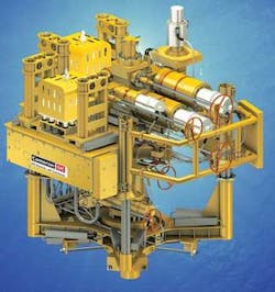
An equipment schematic.
Early in the development process, several analyses were performed to assess the design’s robustness and economic viability, and the results were used to drive updated design parameters and modifications.
During the program’s first five years, several fundamental design criteria were established. Use of direct current (DC) was viewed as a necessity to overcome issues relating to long-distance power transmission. Step-out distances beyond 400 mi (644 km) are easily achievable, with high transmission efficiency using DC power. The current approach employs the coaxial cable for communication at a data rate of 19 kbit/s.
In future, Cameron plans to turn to fiber optics for greater bandwidth and longer step-outs.
The most reliable method of storing energy for fail-safe actuators is by compressing a large spring. This method renders use of batteries unnecessary, avoiding the need for troublesome battery connections and cabling, and making the system truly fail-safe.
Two high torque brushless DC motors drive the valve open and compress the spring, while two small, low-power-consumption stepper motors hold the valve open by loading a wrap spring clutch. Any loss of power or failure at any point in the system results in valve closure via the powerful spring module.
The motor redundancy, along with a dual-channel position sensor, ensures trouble-free service and high availability under normal operating conditions. The position sensor measures the exact stem position to an accuracy of 0.1 mm (0.004 in.), providing assurance of full valve travel. Also, data such as power consumption, valve position, and motor rpm during each valve actuation are stored in a database and can be retrieved for trending calculations throughout the actuator’s life, or for use in preventive or predictive maintenance.
The all-electric choke actuator includes full dual redundancy, fail-in position operation, a fully rotational non-stepping action, precise stem position sensing, and parametric data storage. Full stem travel can be achieved in 60 seconds. Intermediate positioning involves inputting an absolute value in millimeters or a percentage of travel, leading the actuator to travel automatically to that position and stop. Automatic control of flow rate or pressure can also be achieved using the choke as the final control element in a PID control loop.
All-electric subsea production brings advantages in most scenarios, particularly with an ultra deepwater field, or at a long-distance step-out. Electric motors maintain their high level of efficiency and full torque capability regardless of water depth, unlike hydraulic pressure, which must overcome hydrostatic seawater pressure.
Using high voltage DC for long-distance power transmission is far more efficient than either AC power or hydraulic pressure. Even at distances beyond 500 km (311 mi), the efficiency of DC power is 80-90%, compared with less than 20% for low frequency AC. This allows the size of conductors required in the umbilical to be reduced. Also, by incorporating a seawater return system, only one DC conductor is needed, compared to three for three-phase AC.
Removing hydraulic tubing from the umbilical and lessening the number of conductors brings several advantages. The all-electric umbilical has a smaller cross section, allowing longer continuous lengths to be manufactured and spooled. Overall weight also is reduced, facilitating use of a smaller installation vessel. And on very long step-outs, splices in the umbilical can either be reduced or dispensed with altogether.
However, the chief benefit of a smaller, simpler all-electric umbilical lies in its purchase and installation costs. The investment can be reduced further by doing away with the need for control fluid and a high pressure unit (HPU).
Block diagram of main CameronDC components showing parallel redundancy.
Delivering more electric power subsea than is actually consumed is inefficient and shortens the subsea regulation equipment life. The CameronDC surface power supply output voltage and current levels both can be adjusted independently. Output voltage is set automatically to deliver 3 kV at the input to the subsea regulation module, regardless of losses through the cable and connectors.
Output current varies depending on load requirements. In the “idle” state, when only the subsea electronics and sensors are being powered, the current level is low. But when demand increases, i.e. when opening a valve, the current level rises and then stabilizes during the opening sequence. Typically this operation lasts around 1 minute, the current reducing again upon its completion.
Redundancy at the surface is provided within the power cabinet, in the form of dual modular power supplies running in parallel, and via two surface units in a channel ‘A’ and `B’ configuration. This parallel independent channel configuration carries through to the actuator, guaranteeing the system’s operability despite any single point failure.
Two subsea modules, both ROV-retrievable, regulate power and control tree and manifold functions. The first module reduces and regulates the 3-kV input to 300 V DC and separates the communication signal from the power conductor. The reduced voltage and the independent communication signal then pass to the electric subsea control module, which controls valve functions, logs actuator parametric data, receives sensor data, and communicates with surface control equipment. A fully populated control module can operate currently 16 functions.
As CameronDC is also a new technology in the subsea completions line, the company decided to implement a rigorous qualification program. Three levels of testing covered all equipment items from the smallest electronic circuit board to large main assemblies. The tests and their parameters were determined by international standards or by past experience where no standard applied.
The first level of testing applied to electronic printed circuit boards. This was conducted in accordance with ISO-13628-6 at Q1 level. The second level of testing was at the sub-assembly level, and included multiple PC boards mounted in a rack or stacked and other smaller assemblies used to build the major assemblies. For these units the level of testing was also in accordance with ISO-13628-6, but at Q2 level.
In this case, tests were performed at slightly lower shock and vibration levels, because the mass of equipment under test was higher. Also, the main purpose of this test was to verify the integrity of the assembly methods and connections.
A third level of testing was performed on each major assembly. This included each size gate valve, choke, power regulation and control module (PRCM), the electric subsea control module (eSCM), and the electrical connectors and jumper assemblies.
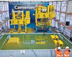
K5F equipment under test at Cameron’s facility in Celle, Germany.
After all the equipment had been fully qualified, a series of integration tests were performed in stages to ensure interoperability and to verify software operation. The first stage (Phase 1A) comprised a surface power supply and surface modem driving through a cable length simulator to a variable electronic load and subsea modem in a non-redundant configuration.
On completion of this test, Phase 1B replaced the simulated load with actual subsea equipment including the PRCM, eSCM, and electric actuators still in a single channel. The final level of testing was Phase 2, which duplicated all the power and control elements forming a fully dual-redundant system in a channel A/channel B configuration. This additional testing was critical to prove that the fully qualified components functioned properly when integrated.
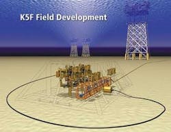
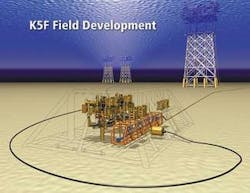
After completing field trials in 2004, Cameron received its first commercial order in June 2006 from Total Nederland for the supply of two subsea trees, including associated all-electric production controls, to be installed inside a three-slot manifold in the K5F field in the Dutch North Sea. The contract also specified that the subsea production controls should be prepared for a future third tree inside the manifold, as well as for a future step-out of a fourth christmas tree assembly. The distance between the host platform and the manifold is 20 km (12.5 mi).
The DC current path uses the coaxial cable inside the control umbilical for the supply of power and communication, and employs sea water as its return path, with four-off anodes at the platform and four-off cathodes at the manifold. Four electrical power and communication units (EPCUs) provide a fully redundant (channel A and B) supply for the four-off PRCMs. These in return send the power and communication signals, after regulating this down from 3kV DC to 300V DC, to the four-off eSCM which is responsible for controlling the valves, choke, and tree instrumentation.
Due to implementation of the all-electric production controls an all-electric DC IWOCS also had to be designed, built, and tested. This system is designed to a general specification to make it fit for use on other applications. It allows either direct control of the individual actuators by a connection at the back end of the actuators, it can control a complete tree through the eSCM by connecting up to the diver interface panel at the front of the tree, or hydraulic over-ride by applying hydraulic pressure on the spring module piston.
Aside from the tree being all-electric, the downhole safety valve (DSHV) is one element in this first project still operating in a traditional hydraulic manner. Operation is effected through use of a tree-mounted solenoid valve assembly, controlled directly by the eCSM. However, Cameron is in talks with various DSHV suppliers and hopes to have the first fully qualified DSHV available by end-2008 to early 2009.
