Steve Smith, Niels Affourtit - Zeetech Engineering
For high-pressure, high-temperature pipeline systems design, the potential for global buckling must be considered and mitigated. Standard solutions cannot be adopted universally without due consideration to construction methods and costs.
The detailed design of the new Offshore Associated Gas (OAG) offshore pipeline system in the UAE is one such example, where considerable project cost savings result from measures taken to control global buckling behavior.
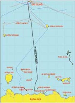
The OAG project forms part of a strategic plan by Abu Dhabi Gas Industries Ltd (Gasco) to link offshore gas reserves to onshore processing centers. As part of this plan, excess gas from the Das Island facilities is transported via a 117-km (72.7-mi) long, 30-in. (762-mm) diameter subsea pipeline making landfall at Ras Al Qila on the UAE mainland. From there it enters the onshore section via a valve station, for onward transport to the Habshan facilities.
National Petroleum Construction Co. (NPCC) was awarded the engineering, procurement and construction contract, with Zeetech Engineering the sub-contractor for design and detailed engineering.
The pipeline is designed to transport sour gas at a maximum flow rate of 960 MMcf/d, a design temperature of 100° C (212° F), and a pressure of 171 bar. Although these conditions are not extreme by current offshore engineering standards, the maximum design temperature and elevated temperature profile expose the pipeline to the possibility of global buckling behavior, with the risk of yielding or local buckling of the pipeline wall.
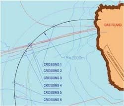
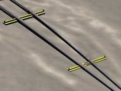
The pipeline leaves Das Island via a 2,000-m (6,561-ft) radius curve, crossing over four existing subsea pipelines and a cable, necessitating support above the seabed at these points in the form of support sleepers. However, the crossings impose vertical imperfections in this hot-end section of the line and create locations where potentially damaging global buckling behavior may occur.
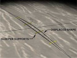
The solution involved inducing lateral movement of the pipeline at five specific initiation locations that coincide with the pipeline crossing constructions. The latter are designed to create soft spots within the system which the pipeline will naturally feed into. This axial feed-in process, and the global curvature of 2,000-m radius, causes the pipeline to laterally displace over the support sleepers of the crossings, resulting in a controlled and predictable reduction in axial compressive force along the length of the approach curve.
Selection of this method to counter potential buckling, rather than the more traditional approach involving expansion spools, resulted in significant cost savings in installation work.
Buckling control options
Significant compressive force can build up in a pipeline subjected to high pressure and temperatures due to the restraint of thermal expansion caused by soil friction forces. As a consequence, the pipeline tends to relieve the compressive force by seeking a secondary equilibrium configuration, i.e. buckling laterally or snaking. The main force holding the pipeline in place is the soil lateral friction restraint combined with the pipeline stiffness.
Pipeline global buckling can be controlled in a number of ways:
- Fully restrain the pipeline laterally and vertically and lock in the axial compressive load, achieved through trenching or physical supports
- Allow a lateral buckle to take place and predict the expected displacements and loads
- Allow the pipeline to displace in a controlled and pre-defined manner at known locations.
Two options were considered for the Das Island project, both involving the controlled reduction of axial compressive force at a known location. The simplest and most predictable was to install welded U-shaped expansion loops at either end of the approach curve, allowing the pipeline to freely expand and in the process reduce the axial force.
This solution would entail hyperbaric welding as the subsea system must be fully welded with no flanges. However, the requirements for hyperbaric welding would have significantly increased installation costs, so the alternative approach was investigated which called for controlled lateral displacement at the crossing locations.
Following initial screening studies, the design team decided to take advantage of the pipeline’s installed radius of curvature and the vertical crossing constructions to create soft spots in the system which the pipeline would naturally feed into. This process results in a controlled and predictable reduction of axial force to below the critical value at which global buckling occurs. The critical buckling load was determined to be approximately 400 metric tons (441 tons).
Analysis was complex and challenging due to the interaction between several variables and the multiple uncertainties associated with the input data and geotechnical complexities. Detailed soil, routing, and seabed data were employed as a basis for developing non-linear finite element models, using ANSYS software, to simulate the pipeline-to-seabed interaction under operating conditions.
The aim was to predict accurately the displacement behavior of the pipeline under maximum operating conditions, to ensure all stresses/strains, displacements, and axial forces were kept within allowable limits and to determine the maximum loads imposed on the support sleepers. The analysis was carried out in accordance with DNV-OS-F101 requirements. The plastic behavior of the pipeline was defined by a stress strain curve de-rated for temperature effects.
Due to the uncertainty in the friction coefficients and pipe-to-soil interaction, upper and lower bound coefficients were assessed and a load case matrix developed in order to determine the critical combination of pipeline /soil and pipeline /sleeper friction coefficients. This defined a reliability envelope in which the pipeline could safely operate.
The behavior of the system is controlled, to a large degree, by the friction developed between the pipeline/soil/sleepers interfaces. To create a soft spot at the crossing locations, it is critical to reduce the lateral friction force restraint on the sleepers to well below the pipeline-to-soil friction of 0.6, i.e. the pipeline is “encouraged” to move over the sleepers rather than over the seabed.
This was achieved firstly by reducing the pipeline’s concrete thickness from 80 mm (3.15 in.) on the seabed to a minimum of 30 mm (1.18 in.) over the crossings. This reduction extends over a distance of 100 m (328 ft) each side of the crossing point. Friction was further lessened through avoiding direct contact between concrete coated pipe and sleeper, by placing a high-density polyurethane (HDPE) layer on top of each sleeper. To achieve an HDPE/steel interface, a 4-m (13.1-ft) long steel sleeve was attached to the underside of the pipeline at each sleeper location over the concrete coating. The resulting lateral friction coefficient is 0.3.
At each crossing location, the pipeline is supported on concrete sleepers ranging in height from 790-1,250 mm (2.6-4.1 ft). The maximum length of the sleepers varies between crossing locations and ranges from 12.1-14.4 m (39.7-47.2 ft). For heights of less than 0.4 m (1.3 ft), steel sleeper supports are used instead of concrete.
Pipeline-to-soil interaction was modeled using non-linear axial, lateral and vertical springs, the stiffness of which represents soil frictional restrain and bearing capacity. The interaction between the pipeline and the concrete support sleepers was modeled using contact elements and a friction factor ranging between 0.2 and 0.5.
Results of the analysis indicated that the pipeline would freely expand into all five initiation locations, with the magnitude of lateral displacement governed mainly by the pipeline operating temperature. The maximum lateral displacement is 8 m (26.3 ft).
As a result of the displacement, axial compressive force reduces from the fully restrained value of 1,500 to 200 metric tons (1,653 to 220 tons) on the seabed and 100 metric tons (110 tons) within the crossing, well below the critical buckling value of 400 metric tons (441 tons).
The robustness of the system was also assessed by assuming that only three locations would activate lateral movement, rather than all five. This situation would lead to additional pipeline feed-in into the three active locations, generating larger lateral displacement and moments. The results indicated that the system has sufficient reserve to absorb this situation safely and maintain loads to within allowable limits.
The authors thank Gasco and NPCC for permission to publish this article and for their contribution to the solutions adopted and for the help and assistance given by Zeetech colleagues.
