Marcos Pellegrini, Giovanni Colodette - Petrobras
Ignácio Martinez, Leandro Neves - Baker Hughes Centrilift
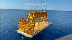
Through technological advances in ultra deepwater production, the highest horsepower-equipped electric submersible pump (ESP) to date was installed in the 1,400-m (4,593-ft) JUB-6 subsea well in the Jubarte field, offshore Brazil. The system is composed of a 1,200 hp motor and a pump capable of producing over 22,000 b/d of heavy oil (17º API). High flow rates and a longer subsea step-out were the drivers for selecting an ESP system as the artificial lift method for the project. Reliability is one of the main concerns of ESPs, and proper selection of the system for the application was critical for the run life of the equipment.
Operators and service companies are always searching for most cost-effective methods to produce deepwater reserves over the life of the field. Gas lift traditionally has been the preferred artificial lift method in offshore Brazil subsea applications with relatively short step-outs. But when high-flow production of heavy and viscous oil in a long step-out is needed, gas lift is not efficient. Electrical submersible pumping systems are the best option.
Jubarte field
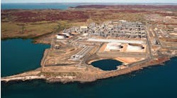
The Jubarte field, in the northern part of the Campos basin, about 80 km (49.7 mi) offshore from the state of Espírito Santo, was discovered in January 2001. An extended well test was performed to evaluate drilling, completion, artificial lift technology, and to verify reserves. Then, Petrobras started Phase 1 production with FPSOP-34. Four wells were planned to produce around 60,000 b/d of oil. Two of the wells are produced using gas lift, the third one is an ESP installation on the seabed, and the fourth is a subsea ESP wellbore installation.
Well description
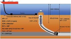
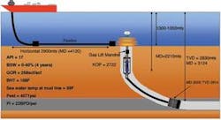
The subsea ESP well has a 7-in. (17.8-cm) production column (26 lb/ft, inside diameter (ID) 6.276-in.). The string is carbon steel except for the downhole safety valves (9% Cr), and the pup joint, crossover, and adjustable union above the safety valve (13% Cr). Long horizontal lengths, around 1,000 m (3,280 ft), were drilled to achieve a high productivity index. An open hole gravel pack (OHGP) was used for sand control.
Gas lift mandrels attach to the tubing string and provide back up artificial lift for the well. If the ESP fails, the gas lift will produce the well until the ESP is replaced.
The well is composed of a 13 5/8-in. (34.6-cm) casing that goes up to around 2,480 m (8,136 ft). The kickoff point (KOP) of the well is around 2,175 m (7,136 ft) from the surface. The ESP was installed at 0° from vertical and is encapsulated in a 10 3/4-in. (27.3-cm) flush joint. A 9 5/8-in. (24.4-cm) liner goes from 2,480 m (8,136 ft) up to 3,130 m (10,269 ft). At this point, the well is in the reservoir. The reservoir, drilled with an 8 1/2-in. (21.6-cm) hole in a 1,000-m (3,280-ft) horizontal section, was completed with a 7-in. (17.8-cm) gravel pack.
Above the gravel packer is a non-returning valve (NRV). This valve prevents injection of brine into the reservoir during an intervention. If the weight of the fluid above the NRV is higher than the reservoir pressure, the NRV is closed, isolating the reservoir. Then, the well can be circulated through an orifice above the NRV with minimal or no loss to the reservoir. The NRV is incorporated in the bottom string and is not pulled during intervention.
A tubing string receptacle installed at around 2,385 m (7,825 ft) completes the lower string.
ESP design factors
The ESP that operated in the Jubarte 17° API heavy oil crude with a gas-to-oil ratio (GOR) of approximately 258 cu f/bbl (.03 cu m/bbl) for approximately one year in the extended well test was pulled and dismantled. Scale found in the pump stages was 86% barium sulphate, 12% strontium sulphate, and 2% iron oxidant.
Also, water analysis was done from two different points and confirmed the quantity of solids present in the water:
Scale formation is a function of the pressure and temperature changes. Forming scale in and around the ESP inhibits heat transfer from the motor to the well fluid, causing the motor to run hotter and to degrade pump performance and increase the risk of locking.
This precipitation must be considered during design to prevent pump damage. To prevent scale deposition, the impellers and diffusers of the ESP were coated with ARMOR I. This is a fluoropolymer coating that makes the nucleation and the growth of scaling difficult and improves the physical properties of the pump stage material by reducing surface roughness and granting better pump performance. The fluoropolymer coating also protects pump parts against aggressive chemical agents and ambient factors.
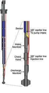
Additionally, to reduce the potential precipitation, continuous injection of an anti-scale chemical through the umbilical and the chemical injection manifold was prescribed with the injection point at the pump intake.
ESP equipment
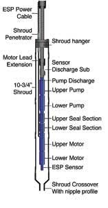
The ESP is housed in a 10 3/4-in. (27.3-cm) capsule with a production rate capacity of 3,500 cu m/day (124 Mcf/d). Petrobras’ design limits and required specifications were:
- Motor not to exceed 1200 hp
- Maximum 200 amps due to subsea penetrator limitations
- ESP to be housed in 10 3/4-in. (27.3-cm) capsule
- Tubing string and ESP carbon steel
- Chemical injection to prevent scale formation, to break emulsion, and for anti-foaming.
The initial considerations for the design and operation of the ESP equipment were:
- Operate within the range of the ESP
- Maximum of 4,500 V. The motor chosen is 4,160 V, and could go up to 64.9 Hz
- Maximum recommended operating frequency of 62 Hz (recommended by the pump manufacturer)
- Minimum starting frequency of 35 Hz, for no more than 30 min. Minimum operating frequency of 40 Hz.
- Compression pump, where stages are fixed to the shaft and all down thrust forces are transferred to the bearings located in the seal section
- Set in vertical position, before kick-off-point (KOP) of the well
- Keep discharge pressure below maximum subsea flowline rating. ESP burst pressure housing is below subsea flowline rating
- Variable speed drive. Operation mode: Filtered pulse width modulation (FPWM) power
- Housing material: Carbon steel
- Scale formation.
All of the design limits required specifications and operation parameters for the pump, motor, sensors, power cable, motor lead extension, shroud penetrator, and capsule were met.
The chemical injection system prevented scale formation and reduced the foamy effect and emulsion. The system design injects the product directly at the pump intake to avoid chemical contact with the non-metallic materials of the ESP (especially from the motor and seal section). A 2 3/8-in. check valve was installed at the base of the ESP.
Natural flow/gas lift through ESP
The traditional presentation of pump performance in the ESP industry is a curve showing the flow as the abscissa and the head as the ordinate. This representation is intended for normal pump operation, that is the pump turning in the correct direction at an appropriate speed, producing positive head (higher at the discharge than the intake) and positive flow (flowing from the intake to the discharge). When a pump stops, and if the weight of the fluid is higher than the intake pressure, the flow will fall back through the pump.
At certain flow, the pump will rotate. The fluid volume must be enough to break the inertia of the pump and motor. The system acts like a generator. If flow rate is enough to rotate the ESP, there are two issues:
- The bearings from ESP operation create a lubrication film between runner and bearing. This film is created by the viscosity of the fluid and the rotational speed. At low speed, there is metal to metal contact that wears out the bearings
- Flowing through the pump, the flow is still in the positive direction, but since the pump is not energized, it is an impediment to the flow and creates a pressure drop. This places the operation of the unit in the second quadrant. The thrust forces in the pump are affected. The pressure created “down thrust” now is negative and acts with rather than balances the up-thrust forces. The stages can be damaged due to the heavy up-thrust forces.
Precautions taken
Each ESP pump has its own four quadrant curve. The curve indicates the limit to start to rotate the stages. As a general rule, -25% to 30% flowrate of the best efficiency point (BEP) at 60 Hz will generate enough energy to start to rotate the pump. The pump from JUB-6 has a BEP of 27,000 b/d, and the well produced around 10,000 b/d natural flow (+37% of BEP). This is above the maximum recommended rate for the pump. But, there is a curve for each pump and motor, and testing is recommended.
Y-tools have been used for dual completions and also to produce a well through the ESP pump. In the case of a capsule, or even a packer above the ESP, there is the option to use tools such as shrouded hydraulic sliding sleeves or others that help to by-pass the pump when it is stopped so as to maximize the production since it would not be limited to producing the well through gas lift or natural flow. This is being analyzed since there is the potential for the tool to fail if it is added to the string. Reliability must be the first concern in a subsea installation.
Acknowledgments
The authors thank Petrobras for its support in publishing this paper.
Editor’s note: This is a summary of the February 2008 DOT paper, 1200 Horsepower ESP Subsea System Offshore Brazil Enhances Production at Jubarte Field, which was presented at the George R. Brown Convention Center in Houston.
The upper string is composed of:
- Tubing string connected to the lower string (gravel pack assembly) through the TSR
- Tubing is 7 in. (17.8 cm) and 29 lb/ft
- An orifice in a gas lift mandrel at the bottom of the string is used to circulate brine during intervention to clean the string
- A compig system (manufactured by ProductionQuest) pressure and temperature gauge sensor (PDG) monitors the reservoir. A T-wire cable (11 x 11 mm) (.43 x .43 in.) encapsulated in epoxy to improve resistance against hits runs from the wellhead to the sensor
- The ESP is encapsulated in a 10 3/4-in. (27.3-cm) flush joint capsule at around 2,100 m (6,900 ft) from the surface. The T-wire cable to the PDG passes outside the capsule up to the mandrel. Special stamp clamp protectors were manufactured to hold and to prevent damage to the T-wire cable (feeding the PDG) through the capsule
- A gas lift mandrel with a 3/8-in. (0.95-cm) orifice is installed above the ESP capsule to produce the well through gas lift in the event the ESP downhole equipment fails
- A downhole safety valve (DHSV) is above the wellhead hanger
- An adjustable union orients the cable to the hole of the wellhead hanger.
The excess cable slack is removed after the connection of the subsea penetrator. This tool is capable of orienting 360° with a maximum misalignment of 30° and has a maximum stroke of 24 in. (61 cm).
