Fault tolerant, hot swappable subsea control architecture can improve reliability
Rick McLin
Rockwell Automation
Subsea control system architectural concepts can be designed to increase reliability and availability. Failure of a single subsea electronic module (SEM) does not have to shut down production nor does it have to reduce the safety integrity level (SIL) of the system. If repair is delayed due to weather or lack of surface-support equipment availability, subsea production can remain operational indefinitely.
Recent incidents have increased public awareness of potential hazards. This heightened awareness can only increase scrutiny from government organizations charged with overseeing offshore and subsea production. Regulation phrases such as "best practicable technology" from the Clean Water Act of 1977 place the onus on the operating company for safety and environmental protection. These requirements will become more stringent in the future.
Having the option of a TÜV-certified SIL 3 fault-tolerant subsea system that complies with IEC61508 and IEC61511 – while also meeting ISO 13628-6 for subsea production-control systems – is a step forward in "best practicable technology."
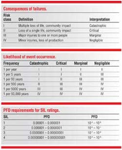
Fault-tolerant subsea control and safety systems are extrapolated from onshore installations where they help protect workers and the environment from hazards. Fault-tolerant safety systems are intended to be the final safety-protection layer. Requirements for these systems were formalized in 1998 with the publication of IEC 61508 "Functional Safety of Electrical/Electronic/Programmable Electronic Safety Systems." The committee that developed IEC 61508 realized that a large part of this standard involved classifying the hazards and risks associated with a process, as well as the likelihood that an event might occur. This resulted in the development of risk categories and the possible consequences of an event on people and the environment.
These consequences are quantified further by estimating the probable frequency of an event.
The IEC standards are further broken down by industry. For example, the process industry is also covered by IEC 61511 "Functional Safety – Safety Instrumented Systems for the Process Industry." IEC 61511 covers the application of electrical, electronic, and programmable electronic equipment use in Safety Instrumented Systems. IEC 61511 defines the concept of a Safety Integrity Level (SIL) to define risk-reduction levels. The most widely recognized certifying organization for Safety Instrumented Systems is TÜV. (TÜV is a German acronym for Technischer Überwachungs-Verein, which in English means Technical Surveillance Association). SIL is basically a design requirement for analyzing the process, as well as a performance standard for the hardware.
SIL requirements for hardware are based on an analysis of Probability of Failure on Demand (PFD). Stated more simply: Will the system operate correctly when required? SIL values range from "1" to "4", with "1" being the lowest and "4" being the most difficult to achieve. PFD requirements are defined for each SIL rating used in an industrial continuous process.
SIL 1 can usually be achieved using standard hardware augmented with some combination of hardware and software diagnostics. To achieve a SIL 2 rating or higher often requires hardware redundancy, along with enhanced diagnostics that provide detailed information on system health.
Topside applications
Topside system equivalents that meet SIL 3 requirements have been widely deployed in the petrochemical, refining, and oil and gas production industries since the publication of IEC 61508. The most successful solutions developed in the 1990s were based on triplicate hardware platforms. Triplication of CPU and I/O allowed sophisticated voting schemes that provide greater fault coverage and diagnostics. This voting approach in a triplicated system is called 2oo3 (2 out of 3). A triplicate voting architecture provides a fault-tolerant capability that allows continued operation of the safety function, even though faults are present in the system.
Triplicated systems support hot swapping of failed components without shutting the system down or degrading performance. This is referred to as triple modular redundant (TMR).
An input from the field proceeds along three independent paths through the TMR system. The inputs are presented to each of the three logic solvers. The logic solvers vote on the validity of inputs and perform whatever logic is required by the application. Results of the three logic solvers then are sent to the output modules and each output module votes the results. The voted output is then sent to the final field device. At any point in the chain, any disagreement is resolved by voting and any errant module's output is not acted upon. In other words, two out of three signal paths must agree on a course of action.
TMR hardware triples the number of components, increasing system size and cost. Often, that increased cost can be justified solely by providing the ability to repair the system online, allowing a critical process to safely remain in service. Any process that has a high cost associated with an unscheduled shutdown is a potential TMR application.
Simplex and dual systems
While TMR systems provide significant operational advantages, their cost and size make them difficult to justify for lower SIL applications. With advances in hardware and diagnostic software, higher SIL compliance without triplication has become possible. Even a simplex system can achieve SIL2 coverage if it has additional diagnostics coverage coupled with a second method to insure a safe shutdown.
The simplex 1oo1D (1 out of 1 with diagnostics) system meets the requirements for SIL2, because the diagnostics can detect a hardware fault and initiate a shutdown to insure fail-safe operation.
A 1oo1D system cannot continue operating in the presence of a diagnosed fault, so it must initiate a shutdown. Obviously a 1oo1D system does not support hot swap of failed modules.
Because the logic solver drives the diagnostics, a 1oo1D system cannot have complete diagnostic coverage. The addition of a second processor improves diagnostic coverage to the point that a simplex I/O with dual processors is capable of providing SIL3 fail-safe coverage.
Failure of any component in a SIL3 fail-safe system necessitates a shutdown. Failure of one processor would degrade this system to a 1oo1D, SIL2. If the process can operate at SIL2 for a short time, a failed processor could be hot swapped to restore SIL3 fail-safe coverage. Any failure of input or output modules would still require a shutdown.
By adding a redundant I/O to the design, a fully fault-tolerant SIL3 system can be achieved. While not as robust as a TMR system, this approach has the benefit of graceful degradation on module faults and supports hot swapping.
This architecture is widely accepted in the topside process industries and is available from many manufacturers.
Subsea control developments
Earlier subsea production control and safety systems were mounted primarily topside, with communication links to I/O installed subsea. The nature of these installations has evolved as more processes have moved underwater. Gas/liquid separation, pumping, and subsea compression require high-speed response, so closed-loop control cannot be accomplished with the communication delays inherent with topside mounting. This need for speed has helped delay the use of subsea applications requiring these features. A number of issues must be resolved before a more autonomous subsea control and safety system can be deployed.
Adapting topside technology
All the architectures presented can provide SIL2 or SIL3 coverage. The challenge is to adapt topside technology for subsea use. Subsea control and safety systems are housed in SEMs, which maintain a nitrogen atmosphere for the electronic components. Space is at a premium in SEMs and electrical wiring penetrations to the module are expensive. The redundant field devices required to achieve a certain SIL rating doubles the number of wires and vessel penetrations.
It is also far easier to environmentally harden and miniaturize topside equipment than it is to design and build new subsea enclosures. Most topside systems are mounted in standard cabinets, usually 19-in. (48¼ cm) wide. Box depths vary. Meanwhile, a SEM requires ROV installation and removal hardware and procedures. Topside installations do not suffer from the same vibration and environmental extremes as the subsea equipment, but they are critical factors for subsea systems.
To fit SIL-rated topside systems into existing subsea enclosures requires a redesign of topside hardware into a Eurocard form. Eurocard is a standard size electronic circuit board supported by all current SEM designs. It can meet the challenge of subsea requirements.
The reduced Eurocard size makes it difficult to find space for hardware triplication, eliminating TMR architectures from consideration. Dual systems, while smaller, still are too large to deploy in a Eurocard SEM. The lowest level SIL3 architecture possible is the redundant CPU SIL3 fail-safe. This architecture requires only one additional module over a simplex design, so the additional space necessary to achieve SIL3 is minimal.
The requirement for redundant field devices poses another problem for a subsea SIL3 system. Doubling I/O increases the size of the I/O modules and doubles the size of the wiring bundles. An obvious solution: Use two SEM enclosures, each with a redundant SIL3 fail-safe system.
By providing two independent SIL3 fail-safe systems, the required hardware can fit within existing SEM enclosures. The problem now becomes coordinating two independent systems subsea.
Communications and diagnostics
The coordination of two independent SIL3-rated systems requires secure communications. The dual SEM architecture shows SIL 3 "black channel" communications links. (While Ethernet is shown, the communications media itself performs no safety functions and can be considered a "black box," hence the name black channel.) TÜV requirements for black channel-certified communications are designed to detect errors from loss, insertion, repetition, incorrect sequence, corrupted data, delay, and other communications faults.
The SIL 3 black channel allows I/O and diagnostic information to be exchanged between SEM A and SEM B. Proper application design can use this to improve system availability. Each SEM exchanges all system health information, all I/O information, and the status of each field device. If SEM A has a failed field device, it can use the data from a healthy device connected to SEM B to continue operation. This exchange of information over black channel communications improves fault tolerance without impacting operation or safety. If an entire I/O module fails on SEM A, it can still continue operating using data from SEM B.
Achieving fault tolerance
While individual modules within an SEM cannot be replaced, an entire SEM can be removed while the subsea production facility remains in operation with no reduction in SIL rating. Fault-tolerant SIL3 hot swappable subsea control systems are feasible with the proposed architecture.
Hot swapping control modules subsea is only possible if each SEM is in a physically separate location. An ROV obviously must access a failed SEM to replace it. A subsea hot swappable system must include the ability to gracefully remove and reinsert a SEM. This removal and reinsertion must be bumpless, with automatic education and synchronization of the new SEM with current operating data. Not a trivial task, but achievable.
Even though the SEMs are physically separated, they still function as a single system. This requires that the application software in each SEM not only exchange diagnostic information, but be capable of both independent and combined operation.
Redundant topside communications channels may or may not be black channel, but diagnostic data from each SEM can be transmitted topside. This provides redundancy in topside communications and offers an alternative data path if topside links to one SEM fail.
If the SIL 3 black channel Ethernet between each SEM fails, then the topside monitoring system would need to look at the status of each SEM and decide which should continue operation. Loss of communications to a single SEM causes no degradation of system performance since communications topside is maintained through the second SEM. Multiple data pathways increase overall system availability.
If both SEMs lose topside communications, all subsea operations could be immediately shut down, or a predetermined interval could elapse before shutdown occurred.
