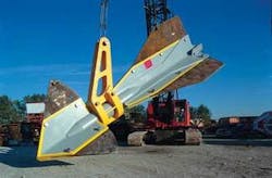
A new design of gravity installed mooring anchor addresses two issues involved with using such anchors for mooring. Its design requires less soil penetration to be effective, and its mooring line attachment method reduces some potential installation problems. The key design features are a 360° rotating load arm and retractable fluke fins.
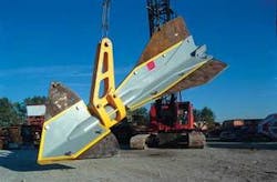
Test anchor upon completion of fabrication.
The hinged load arm design makes the rotational orientation of the anchor unimportant. The load arm can rotate toward the load application angle, and in cases where mooring systems would have a range of angles, the anchor load arm can adjust without significant differences in holding capacity. The mooring line attachment can rotate completely around the body of the anchor. This also reduces the chances of the mooring line catching on the anchor plates.
The retractable fluke fins allows the anchor to be tailored to rotate into the soil and to begin diving at a preferred tension level. Once significant load is applied to the anchor, the anchor begins to rotate into the soil until the lateral resistance of the lower fluke fins becomes equal to the lateral resistance of the upper fluke fins. Once this level of loading is exceeded, the anchor performance becomes driven by its axial capacity, and it begins to dive deeper into the soil at a trajectory.
This trajectory is a function of the uplift angle at the anchor. Under its current configuration, the anchor will continue diving at uplift angles in excess of 45°. The anchor continues to dive until the resistance of the soil is equal to the load being applied. The key of this performance is that under extreme loading, the anchor will not fail catastrophically, but will continue to dive until the needed capacity is supplied.
Once proven, this anchor offers performance when pulled from virtually any radial angle. In extreme events, such as a mooring line break, the anchor provides additional opportunity to hold the rig on location while reducing the probability of dragging a mooring anchor across the sea floor.
Heretofore, gravity-installed anchors required significant penetration into the soil to generate adequate holding capacity. With the MIG anchor, penetration generally is sufficient at just past its full length, which is half that of many other gravity installed anchors.
Further, in comparison to the generally circular cross section main shafts of most gravity-installed anchors, the MIG’s multiple channel central body tends to channel the soil into the “V” of the channel member, thereby compressing the soil rather than spreading it as with a cylindrical shaft. This gives the anchor improved dive and holding capacity.
Anchor installation
The anchor is lowered to 76 m (250 ft) above the seafloor installation target. The anchor is then acoustically released from the lowering rigging and allowed to freefall through the water column below and into the mud to full installation embedment. Once installed, the anchor line stem is attached to the subsea connector, and the load arm is orientated to the proper heading for the mooring application. The anchor requires only minimal bollard pull to adjust the load arm and no bollard pull to set the anchor. Another advantage is that the MIG anchor is only half the size of a comparable suction pile anchor, thus allowing for the installation of twice as many anchors in a single mobilization
Shell test
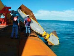
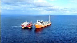
A Shell-sponsored offshore test established the offshore installation ability of the MIG anchor. During the test, the anchor was safely deployed and recovered from an anchor handling vessel. The test also confirmed that the anchor will freefall at the angle it is release from and within a very small margin of variability, making it stable during freefall.
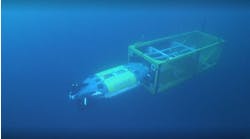
MIG anchor being dropped during a test run by Shell.
The test took place in Vioska Knoll, in about 427 m (1,400 ft) of water. The anchor was the full-size version. The anchor is 9 m (30 ft) long with about a 3-m (9-ft) fin span with a dry mass of 34,019 kg (75,000 lb). The design capacity of the anchor (structurally) is about 816,000 kg (1.8 million lb) for this MODU model. The anchor technology can be sized and adapted to be used for pipelines and permanent facilities. The sea floor at the test site was a typical Gulf of Mexico soft to medium clay.
A second test is scheduled with for January of 2007. It will be conducted by Anadarko near one of its spar production facilities where the soil conditions are well known.
The design of this anchor allows the user to vary the exposed nose and tail plate areas as required for various applications, soil types, and soil strength gradients.
Evan H. Zimmerman
Delmar Systems Inc.
