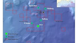
The Ormen Lange gas field lies 120 km (75 mi) northwest of Kristiansand on the west coast of the Norwegian mainland. The development route traverses water depths ranging from 250 to 1,200 m (820-3,937 ft), the most challenging section being the Storegga slide region. Here the seabed is very irregular, with soil conditions varying from very stiff clay with boulders to soft clay.
Operator Norsk Hydro opted for a subsea tieback, around 120 km (75 mi) long, directly to the shore-based processing terminal at Nyhamna, with gas exported from Nyhamna to the UK via the Sleipner complex in the North Sea. Ormen Lange represents Norway’s largest single offshore investment to date and will be the country’s second largest gas field in production when exports to the UK get under way in October.
Laying the lines
Hydro awarded Acergy the contract for the MEG pipeline installation in May 2004. The scope of work covered laying and commissioning of two 120-km (75-mi), 152-mm (6-in.) pipelines from Nyhamna to the Ormen Lange subsea manifold in water depths ranging from 0 to 850 m (0-2,789 ft), in addition to a 3.6-km (2.2-mi), 152-mm (6-in.) infield line between the two production manifolds.
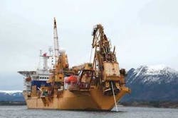
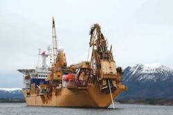
For this work, the contractor proposed the dynamically positionedAcergy Falcon, which can install rigid lines up to 356 mm (14 in.), diameter in J-lay mode in water depths up to 1,500 m (4,921 ft). The vessel welds the pipe joints in an onboard firing line, and can carry joint loads of up to 2,000 metric tons (2,205 tons), which can be re-supplied during operations offshore.
The vessel also features a flexible flowline lay spread: flexibles can be stored in a 1,600-metric ton (1,764-ton) capacity powered carousel or on reels on deck. Two onboard work-class ROVs are used for touchdown monitoring and survey purposes.
The 50-year design life of the Ormen Lange pipeline system led to a requirement for a three-layer polyproplylene field joint coating system, including an inner layer of fusion bonded epoxy. Although theAcergy Falcon had not deployed such a combination before, the company developed a suitable system for this project in association with subcontractor PIH, which resulted in high quality field joints and low cycle times.
Project challenges
Among the main issues regarding installations in the Storegga slide area were:
- A combination of extreme seabed topography and non-homogeneous soil conditions
- The impact of the steep slope down the slide escarpment on pipelay and intervention work
- High current velocities and directional variations through the water column
- Uncertainties regarding current velocities, distribution, and direction, especially in the more severe topographical section
- Tight installation tolerances for the pipelines
- Thermocline (the effect on survey results caused by differences in densities down through the water column)
- Deepwater location of the field (more than 850 m [2,789 ft]).
At its most problematic, the seabed route features steep slopes in both longitudinal and transverse directions, combined with a strong current in the entire water column. This current is also liable to surge without warning, so the installation vessel must be ready to change system settings at short notice.
The rough seabed bathymetry necessitated an intricate route for the pipeline comprising various tight lateral curves (down to 500 m [1,640 ft] radius), connected in between only by short sections of straight pipelay. Further, the route demanded a very accurate laying tolerance to hit pre-laid rock berms and pre-cut trenches. This combination meant that a low bottom tension had to be adopted to avoid pulling the pipe out of its dedicated laying corridor.
Another side effect of rough terrain is the occurrence of freespan when the pipe rests on the seabed. A low bottom tension is also necessary to keep the length of each freespan to a minimum. TheAcergy Falcon can alter the angle of the lay ramp during laying from shallow to vertical, allowing it to adjust lay parameters such as bottom tension to the project’s requirements.
When the vessel performed pipelay down the steep Storegga slide - a 30° slope from 250 m to 650 m (1,640-2,133 ft) water depth - pipe was installed with bottom tensions of less than 1.5 metric tons (1.7 tons), with a high use of moment capacity in the sag bend. This was necessary to reduce the length of some very long free spans and therefore also the seabed intervention cost.
To this end, static and dynamic analyses were performed for various water depths, seabed terrain, and environmental conditions, taking into account the vessel’s station keeping and dynamic response capabilities in varying weather conditions.
When the water depth was more than 950 m (3,117 ft), current speeds of almost 1 m/sec (3.3 ft/sec) at the surface and 0.5 m/sec (1.6 ft/sec) at the sea bottom generated several metric tons of drag force on the pipe. This had a significant impact on the configuration of the pipe catenary, especially as the low bottom tension leaves the catenary in a ‘slack’ shape.
Online monitoring
To comply with the tight routing requirements while avoiding over-stress and damage to the pipe, the vessel needed to be able to respond quickly in the event of a current surge. The solution to this requirement was online monitoring of the catenary for installation of the MEG lines.
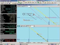
The monitoring system comprised an acoustic Doppler current profiler continuously measuring the current direction and speed through the entire water column. In combination with the vessel and touch-down positions, water depths and pipe angle, this current profile served as an input to a continuous static calculation.
Prior to heading offshore, the company devised tables for most potential current scenarios, taking into account vessel position and ramp angle. These, and the online monitoring system, gave the crew the data needed to take action once the current increased.
During MEG line installation, a strong current coming in transversely to the lay direction forced the vessel to offset up to 90 m (295 ft) from the lay route and also rotate 37° to the laying direction. The monitoring system also captured the residual bottom tension, which was higher when a current was active in the lay direction. The team recorded the residual bottom tension along the whole route from the shore. This information proved vital for the post-lay trenching.
Laying pipe in deepwater with a strong current created another challenge, as the journey each pipe joint had to travel down the catenary before landing on the seabed, together with the rough sea states and strong currents, made the pipeline susceptible to fatigue. Enforced halts for operations such as weld repairs would add further to fatigue exposure in the catenary. When current is present in the water column, vortex-induced vibration (VIV) can occur.
To forestall this, Acergy performed full-scale fatigue tests and fatigue analyses with and without VIV before starting offshore operations. The results of these tests were taken into account when determining the methodology for the project. Wave-induced fatigue was kept to a minimum by factoring analysis results with the vessel’s ability to lay the pipe with low bottom tension (slack catenary) and the low repair rate (63%).
Survey techniques
Ormen Lange is in a hostile environment, and debris from the Storegga slide limited routing options. This necessitated pre-intervention work, including excavation and rock dumping to create passable routes. To limit the scope of both pre- and post-lay intervention, strict lay tolerances were imposed along parts of the route. Additionally, a very low curve radius was selected to avoid the numerous large blocks of clay on the seabed.
What made the operation even more demanding in the lower part of the slide edge was the presence of thermoclines between the cold water at less than 0°C (32°F) at depth, and the warmer water higher up. These thermoclines could have induced errors in acoustic ranges or even blocked acoustic signals completely.
Survey equipment included dual-head multibeam sensors; an inertial system; a long baseline (LBL) acoustic positioning system; a digital terrain model of the seabed from the pre-lay survey; and a high-precision GPS surface positioning system.
The two ROVs onboard theAcergy Falcon can support laying and continuous touchdown monitoring. Both were equipped with the newly introduced survey sensors for this project. Sensors were integrated with the standard survey sensor spread, all operated by the vessel’s regular survey crew. The surveyors also supervise the automated pipelay system that controls the various stations in the firing line and provides input to the dynamic positioning system concerning vessel movement once a pipelay cycle has been completed.
Also onboard the vessel are a Kongsberg HiPAP 500, a super short baseline (SSBL) system to calculate the subsea positions of both the ROV and other equipment relative to the vessel’s location, based on acoustic distance and heading. A GPS system positions the vessel to within 0.5-m (1.6-ft) accuracy.
Another new development to improve acoustic positioning was inertial navigation - using the actual motion of the ROV to calculate the position. Both ROVs were equipped for this purpose with Kongsberg’s HAIN system, which proved effective in reducing noise on the acoustic signal, leading in turn to a more reliable and stable position.
Even with the inertial system, however, SSBL accuracy is affected by water depth, and when depth increased beyond 500 m (1,640 ft), and the required installation accuracy was less than +/- 2.5 m (+/- 8.2 ft), another approach was needed to maintain accuracy.
In this case, the client had installed a large number of Compatts to form numerous extensive LBL networks, providing positioning accuracy within the array of better than 20 cm (7.9 in.). The client opted for Sonardyne’s new medium frequency wideband technology along parts of the Ormen Lange routes.
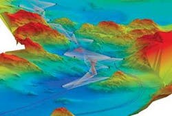
Also,Acergy Falcon deployed dual-head multibeam systems (Kongsberg E3002), used for the first time as an advanced cross-profiler. The systems provided an instant 3D view of the seabed, which showed clearly the 152-mm (6-in.) diameter pipeline in relation to pre-ploughed trenches, other pipelines, boulders, and clay blocks. These images were used to precisely position the line. This, combined with seabed data from the pre-lay surveys, kept post-intervention needs to a minimum.
Pipeline terminations
TheAcergy Falcon remit extended to installation of the four MEG pipeline end terminations (PLETs), each weighing 15 metric tons (16.5 tons). Acergy and FKS engineered these items to optimize installation from the vessel in 850 m (2,789 ft) of water.
FKS also provided the CAT-10 tie-in system for the pipelines. This resulted in the use of a comparatively large PLET that was relatively top heavy. Thin walls on the 152-mm (6-in.) MEG pipelines posed potential problems with regard to the allowable bending moment in the pipe during the installation, bearing in mind the combination of deep water and strong currents.
The solution was a balancing act that took factors such as the position of the installation padeyes, the pipeline catenary weight, the vessel’s position during installation, and the current in the water column into account.
Acergy deployed a static PLET frame for the installation. The frame had been used on several other projects, but had been refurbished to suit the Ormen Lange PLETs. A 120-metric ton (132-ton) winch was also installed inboard of the frame to aid pipeline recovery, PLET-to-pipeline tie-ins, and PLET laydown. A pre-installed 7 m x 14 m (2 ft x 4 ft) steel plate supported the PLETs on the soft seabed.
In total, installation of this 250-km (155-mi) stretch of pipelines and the four PLETs took 108 days.
Editor’s Note: This is an edited version of a paper delivered at the Deep Offshore Technology Conference in Houston, November 2006.
Per Kristian Forbord
Lars Myklebost
Arne Skeie
Gisle Morisbak Lund
Baard Owe Bakken
Acergy Norway
