Lenny Sutherland, Insensys Oil and Gas
A new technique to embed optical fibers within a glass fiber/epoxy composite carrier forms a powerful strain sensing instrument suitable for handling and deploying offshore. Insensys Oil and Gas developed this technique as a result of the exploration and production of oil and gas reserves migrating to deeper water depths presenting increasing demands on the design and operation of subsea infrastructure from unfamiliar operating environments. Integrity management of subsea structures such as risers, flowlines, and other subsea equipment has become increasing important as these operating conditions become more challenging. Key to any integrity management plan is the ability to assess the fatigue performance of infrastructure through measured data.
The composite carrier portion of the instrument provides a number of functions which include; mechanical protection of the fibers during deployment, a pre-finished instrument that can be hydrostatically tested, the ability to verify sensor performance through factory functional testing, and a strong framework that can be simply strapped to the host structure to be monitored during installation (rather than worksite bonding of individual strain sensors).
Fiber optic strain sensors
A variety of measurement methods exist to assess the technical integrity of subsea structures. One technology that has seen a significant increase in use over recent years is the use of optical fiber sensors for direct strain measurement to provide real-time stress and fatigue life condition.
Optical fibers were originally invented for telecommunications purposes and can transmit light over a long distance with minimal loss of light. It was discovered that the properties of the light inside the fiber were affected by physical parameters outside the fiber. This meant that the fiber itself could be used as both the sensing element and the communication path for the signal between the sensor and optical interrogator.
While strain measurement instrumentation using optical fibers has been developed for over 20 years, a breakthrough in the way that the sensitive optical fiber sensors are deployed has led to the rapid adoption of fiber optic strain sensing technology by the oil and gas industry over the last few years.
Fiber Bragg grating sensors
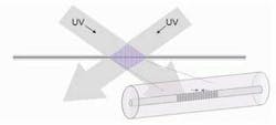
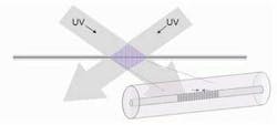
A whole area of optical fiber sensors has evolved around the use of fiber Bragg Grating (FBG) sensors since these components overcome many of the limitations of using standard untreated fiber as a sensor. An FBG is created in the fiber core by illuminating the side of the fiber with alternating high/low stripes of UV light that induces the refractive index change in the fiber. The alternating UV pattern is generated by superimposing two beams of UV light at different angles of incidence to create a spatial interference pattern.
The FBG reflects a wavelength of light that is dependent on the pitch of the stripes in the grating. As tension or compression is applied to the fiber, the pitch of the stripes in the grating changes, and as a result, the reflected wavelength changes. Monitoring the wavelength reflected from an FBG therefore provides an absolute method of detecting point strains at the location of the grating. Given the physical properties of the grating, they are not subject to the same calibration or long-term drift issues associated with electronic resistive strain gauges.
A key advantage of FBG sensors is the ability to place numerous sensors at different locations in a single optical fiber, commonly referred to as multiplexing. By multiplexing sensors in this way, over a hundred sensors can be monitored using a single fiber and optical interrogator. For comparison, 100 resistive strain gauges would require over 300 connections to the measurement instrument to be made.
The patented Insensys fiber optic interrogator system is a compact Eurocard configuration consuming only 3W of power. It uses time of flight to distinguish different sensors in the fiber and can take over 2,000 measurements per second.
Integrity monitoring systems
The monitoring approach developed by Insensys exploits the use of a composite carrier structure with embedded optical fiber sensors, which is then fastened to the host structure to be monitored. The company has developed a range of composite based optical sensor devices that measure axial strain, bending, temperature, and non-invasive pressure. Handling and installing these sensors is analogous to installing strakes onto a riser.
The composite carrier is pre-molded to any shape to fit the structure to be monitored. During manufacturing of the composite structure in the workshop, fiber optic sensors are positioned precisely at predetermined locations. The optical fibers are then embedded inside the carrier to become an integral part of the composite carrier. The surrounding composite material ensures good strain transfer from the host structure to be monitored, plus provide physical protection from the subsea operating environment and potential mechanical damage during installation.
The composite carrier is designed to flex with the host structure, requiring simple clamping to comply with the structure motions. Since installation is a simple operation, the entire monitoring system can be manufactured in a controlled environment to specifications and it can be performance tested before it leaves the factory.
Reliability of fiber optic sensors has further been improved by locating the opto-electronic measurement instrumentation local to the composite sensor carrier where appropriate. These integrity monitoring systems go through a series of field simulated tests including hydrostatic pressure test to working depth and performance accuracy verification tests as part of the standard factory acceptance testing prior to shipping offshore. These tests all contribute to ensuring the instrument will function reliably once installed and operating offshore.
In contrast, electrical resistive strain gauge systems require bonding to the surface of the structure being monitored. The accuracy and reliability of their measurement thus depend on obtaining a high quality, long life bond, in addition to the stiffness of the adhesive system. Even if installation is successful, these surface mounted, fragile sensors have shown to be susceptible to long-term measurement drift and flooding of the sensor electronics particularly in the subsea environment. Ironically resistive strain gauges have historically exhibited poor fatigue performance and often debond from the structure being monitored for fatigue.
Riser monitoring
A range of optical fiber strain sensing instruments have been developed and installed as part of an operator’s riser integrity monitoring program. Applications have included simple shape sensing subCmat’s containing three optical sensors within the carrier oriented in the axial direction to enable two orthogonal bending measurements to be made. Other projects have required axial strain or tension values to be monitored in combination with curvature and temperature data. These monitoring systems have proven valuable for operators, to understand operating stresses and to validate and update their fatigue models.
Operational data from a riser monitoring system will indicate a number of discrete vibrations with a period of between 2 seconds and 8 seconds. The noise of the signal is about one-tenth of a microstrain, equivalent to 0.003 ksi. The high accuracy and strong, reliable deployment has led to rapid uptake of optical fibers for riser monitoring.
Flowline buckle monitoring
The first optical sensing system to be developed for non-riser applications was to continuously record the shape of flowline buckle regions to determine the accumulated fatigue and remaining lifetime for a deepwater project offshore West Africa. High pressure/high temperature (HP/HT) flowlines experience significant expansion and contraction during normal operating conditions. For flowlines above a specific length, the expansion can lead to buckling, which if uncontrolled could lead to failure.
To accommodate the sizeable expansions and contractions of HP/HT flowlines during startup and shutdown, buckling regions are generally initiated at controlled locations. For flowlines in deep waters, where burial and rock-dumping is not feasible or prohibitively expensive, this can be the only practical way to manage flowline thermal expansion issues. High stresses are induced during buckling and repeated cycling can lead to failure by fatigue. Current inspection methods using sidescan sonar or ROV survey capture a snapshot of the buckle at a single moment in time, although provide limited resolution and furthermore reveal nothing about the actual behavior of the buckle between snapshots. Continuous monitoring can give a complete picture of the buckle response to operational cycles and shut-downs. This enables a far more accurate determination of accumulated fatigue, and allows any buckle growth, or movement to be monitored over the life of the field.
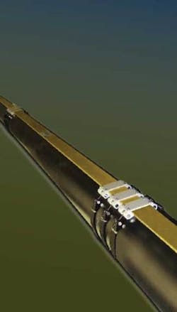
The optical strain measurement technology previously used on risers has been adapted to monitor buckle regions of flowlines. The sensor device is required to measure curvature and shape of the buckle in the lateral direction at a number of positions along its length. The configuration of the sensor arrangement and composite geometry is somewhat different to the riser application in order to accommodate the extensive bending strains of a mode 1 lateral buckle; additionally placing a number of separate sensor carriers along the buckle region is not cost efficient. Therefore, the monitoring solution has a long flat carrier geometry referred to as a subCstrip containing embedded optical sensors along its length.
The strip is clamped onto the pipe either as part of the flowline lay process or in a retrofit installation by ROV. Again the optical sensors terminate into a one atmosphere housing containing the optical interrogator electronics. The system has been configured to send data to the surface via an umbilical, or due to its low power consumption, the system can operate remotely for several years with data periodically uploaded by either acoustic modem or ROV intervention.
Non-invasive pressure monitoring
Pressure measurements of SURF pipelines, manifolds, and associated production systems can be made that are used for the same combination of fiber optic sensors and composite technologies as the riser monitoring instruments. By placing the optical strain sensor in a circumferential orientation within the composite carrier, the hoop strain of the pipe is measured and directly related to internal pressure.
Dynamic tests were also performed on a fiber optic pressure sensor to evaluate its performance for monitoring gas flow induced pressure fluctuations in flowline and associated manifold pipe work. The magnitude and frequency of the excitation was varied up to 600 Hz to investigate the performance of the fiber optic sensor over a wide range of conditions. Noise level results of 0.2 microstrains were recorded, which is equivalent to a dynamic pipe pressure fluctuation of 0.15 bar.
Deployment
Unlike traditional resistive strain gauges, these sensors are fabricated and fully tested before leaving the factory. Their simple clamping installation procedure has enabled operators to install the systems without wasting critical construction or riser deployment time.
The adoption of these fiber optic strain sensors in the oil and gas SURF arena has accelerated rapidly over recent years due to the new method of instrument deployment that provides high accuracy, reliability, and simple handling and installation procedures. The versatility of measurements and ability to deploy the systems in brown field sites has also enabled operators to apply the technology to aging assets as part of recertification and life of field integrity management programs.
