Economics, recovery issues drive choice of subsea compression for Norwegian Sea field
Nick Terdre
Contributing Editor
When Statoil's Åsgard subsea compression system comes onstream in the first half of 2015, it will be the world's first – unless pipped at the post by the company's Gullfaks subsea compression system, due to be operational at around the same time. Not long afterwards, the Ormen Lange subsea compression system could follow, assuming the pilot system performs satisfactorily in tests which began in March.
The Ormen Lange pilot is operated by Shell, but Statoil is a partner and has also acted as technical manager for the development up to the current phase of testing. Its participation in these projects gives it unparalleled knowledge of subsea compression and will be a key factor in its drive to create what it calls a "subsea factory" on the seabed by 2020.
Following concept selection in 2010 and lengthy qualification of compressor units, Statoil and its partners Eni, ExxonMobil, Petoro, and Total committed last year to the NOK 15-billion ($2.6-billion) investment for the Åsgard project. Norway's government approved the plan for development and operation this March.
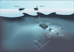
The Åsgard application does not involve a particularly long stepout – the system will be installed on the Midgard field, which delivers gas and condensate to the Åsgard B floating platform some 40 km (25 mi) to the west. Production from Mikkel is also routed through Midgard. The additional recovery that subsea compression will provide from the two fields is estimated at 278 MMboe.
In terms of the concept selection criteria, the subsea solution proved superior to two topside alternatives based on well-proven technology – locating the compression facilities on either the Åsgard B platform or on a new platform on Midgard. According to project manager Torstein Vinterstø, the potential of the Åsgard B option for additional recovery is reduced due to the diminished efficiency of compression at the destination, while a dedicated platform on Midgard would be significantly more costly than subsea facilities, although in terms of the additional recovery it would be not far behind.
Compressor requirements
In December 2010, Aker Solutions was awarded a NOK 3.4-billion ($597-million) EPC contract. The scope covers delivery of the compression station and manifold station, equipment for the topsides, controls, the high-voltage electrical system, and partial responsibility for the total system, said Øystein Haukvik, Aker Solutions' project manager. The system is required to have 96% availability.
One of Aker Solutions' first acts was to contract MAN Diesel & Turbo for four 10-MW compressor units, due for delivery this year. These are being built to the company's proprietary Hofim design, with integrated motors and magnetic bearings, and hermetically sealed. Although rated at 10 MW, it has proved possible to run the units at 11.5 MW, thus achieving greater compression capacity, Vinterstø says.
Two compressor trains will be installed on the seabed. They will operate in parallel, although when production starts to tail off, they could be put to work in series to maximize hydrocarbon extraction. One of the four units will be a spare and the fourth is for testing purposes, although it will eventually also be available as a spare.
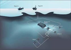
The subsea compression station will be installed about 1 km (0.6 mi) downstream of the Midgard Z template, which also receives the Mikkel well stream, in 250 m (820 ft) water depth. The station, measuring 75 x 45 x 20 m (246 x 147 x 65 ft) and weighing about 4,800 metric tons (5,291 tons), will have capacity to compress 21 MMcm/d (742 MMcf/d) of gas, boosting the pressure of the flow some three times. Upstream of it, the well stream from Midgard templates, X, Y, and Z, will be combined in a manifold station weighing 900 metric tons (992 tons) and measuring 34 x 28 x 9 m (111 x 92 x 29 ft).
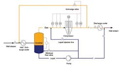
On entering the compression station, the well stream first passes through an inlet/anti-surge cooler. Next it goes to the scrubber, where the gas and liquids are separated. The gas then enters the compressor while the liquids pass through a high-speed booster pump. Before the two streams are recombined, the gas is cooled by the outlet cooler, the function of which is to protect the pipeline from excessive well stream temperatures.
There are nine main modules in each train – the inlet/anti-surge cooler, scrubber, compressor module (the heaviest, at around 300 metric tons, or 330 tons), the pump module, MEG module, the discharge cooler module, the umbilical termination module, the compressor transformer, and the control and power distribution unit (CPDU). All items are individually retrievable, as are other units, mainly instruments and electric actuators mounted on the modules.
On leaving the compression station, the boosted well stream will be transported to Åsgard B by a new 37-km (23-mi), 20-in. (51-cm) export pipeline. To provide redundancy in the export facilities and to reduce pressure loss, one leg of the existing pipeline loop which connects the Midgard templates and Åsgard B will remain in use. A new line will be laid from the compression station to a hot-tap connection into this line.
Various other pipelines will be laid. The templates will be connected to the manifold station by new 10-in. (25-cm) lines, and two new MEG lines will run from the Y template to the manifold station and onto the compression station. It will also be possible for the well stream, partly and wholly, to bypass the compression station, thus allowing complete operational flexibility.
All-electric approach
Power and control for the subsea facilities will be all-electric. An early decision was taken in favor, even before the same decision was made for the Ormen Lange pilot, says Haukvik. A hydraulic system would have been much more complicated to design and to implement. By contrast, an all-electric system is more environmentally friendly, with no fluids that might leak into the sea. Electric actuators are also smaller and lighter than their hydraulic counterparts.
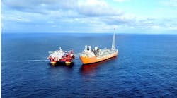
Control of the compression system will be exercised from Åsgard B, although power will be supplied from the Åsgard A production ship. A fiber-optic network will link the two platforms with the subsea system. Communication between the topsides and the subsea facilities will take place through three subsea control modules on each train.
Because of the relatively short stepout, power can be supplied as alternating current and parts of the power system, including the variable speed drives and some transformers, can be located on the ship. Most of the topside equipment will go in a dedicated module weighing 900 metric tons (992 tons).
The total installed power for the system is roughly 25 MW. Power will be supplied from the ship at 24 kV and transmitted to each train by two umbilicals. One will carry power at 36 kV to a subsea step-down transformer, which will feed the HV motor at 6 kV, while the other will transmit 12 kV power to the umbilical termination module from where it will be distributed to the pump string and controls.
The system will be assembled at the Aker Solutions yard in Egersund, Norway, where fabrication of the template for the compression station and the manifold station is also taking place.
There will be several test periods, Haukvik said. Control system testing is due to start in late 2012 in Aberdeen, where the control system is being developed, culminating in a dry system test. Each module will also undergo functional testing. But the main test period will take place at Statoil's K-lab at the Kårstø plant in late 2012/early 2013 when the compressor units – first the test unit and then the delivery units – will undergo robustness verification in underwater conditions.
The final test phase is scheduled for summer 2013 at Egersund, with a system integration test, mechanical testing, and controls testing.
Installation, component contracts
Most contracts have been awarded. The compression station template and manifold station are due to be installed in 2013 by Saipem's crane-bargeS7000, which will also install the Åsgard A module. Module hook-up and topside modifications will be implemented by Aker Solutions.
Technip will manage marine operations, including installation of the subsea modules, umbilicals and fiber-optic cables, and in-field pipelay. Bergen Group Rosenberg will fabricate a riser base and 12 pipeline-end manifolds, with Nexans supplying umbilicals. Allseas'Lorelay will install the new pipeline to Åsgard B in 2013. Among contracts placed by Aker Solutions, ABB will supply topside drives and transformers, Schneider the subsea CPDU, and Deutsch, GE and Expro the HV subsea power connectors.
In March, Statoil still had to decide the intervention strategy. One solution under consideration is a novel side-mounted installation and retrieval package being developed by Technip – it will use this system for the subsea module installation and has an option on its contract to deploy it for intervention. But an alternative could be a specially designed intervention vessel with an enlarged moonpool.
Statoil wants malfunctioning equipment to be replaced within 20 days, and has specified that it should be designed for installation/retrieval in 4.5 m (14.7 ft) significant wave heights, reflecting the harsh conditions in the Norwegian Sea where Åsgard is located.
Ormen Lange synergies
With a stepout of 125 km (77 mi), 850 m (2,789 ft) water depth and, as originally envisioned, a power requirement of 58 MW, Ormen Lange subsea compression differs significantly from Åsgard in some respects.
But the two sets of licensees agreed that there would be mutual benefits in sharing information and seeking to capture development synergies between the two projects. They therefore signed a memorandum of understanding to this effect in 2010. Having the same main contractor in both projects has also contributed to the positive interplay – the two project teams are on the same floor in Aker Solutions's Oslo offices and some personnel work on both projects.
Coming in the wake of the Ormen Lange pilot, the Åsgard project has benefited from lessons learned, but there are still some technology gaps to be filled, Haukvik said. These include the high-speed subsea control network, which has to meet requirements not present on Ormen Lange.
Again, the coolers for the Åsgard system are larger than their Ormen Lange counterparts and have a different functionality.
But the greatest challenges have been in connection with the functioning of the compressor units, which operate in a horizontal position. Work still has to be done to complete the marinization of the compressor units and to upgrade the magnetic bearing system.
As pioneering projects with relatively conservative design criteria, both the Åsgard and Ormen Lange subsea compression systems are expected to offer opportunities to optimize the technology and reduce costs once operational experience has been gained and system reliability established.
The first priority is to bring the Åsgard subsea compression project to a successful conclusion.
"The project team is looking forward with excitement to the day when this system is in operation," said Vinterstø. "In the meantime we move forward with the challenge of making this valuable technology a reality."
Offshore Articles Archives
View Oil and Gas Articles on PennEnergy.com
